Electrical engineering pay-off positioning device

A positioning device, electrical engineering technology, applied in the directions of transportation and packaging, transportation of filamentous materials, thin material processing, etc., can solve the problems of long time, inconvenient operation, waste of manpower, etc. The effect of laying requirements and saving manpower

Active Publication Date: 2021-06-22
安徽祥源科技股份有限公司
View PDF6 Cites 1 Cited by
  • Summary
  • Abstract
  • Description
  • Claims
  • Application Information

AI Technical Summary

Problems solved by technology

[0002] In order to connect the circuit during the construction of electrical engineering, the cables will be reasonably arranged to connect the circuit. During the use of the cable, it is often necessary to wind the cable on the ring winding frame in advance, and release the wire according to the use requirements. At present, due to In the construction of multi-circuit lines, the method of one pull and one pay-off is still adopted. It takes a long time to use a single ring-shaped winding frame and wastes manpower. Under the action of inertia, the winding frame will still automatically unwind the wires and cannot stop in time. It needs to be manually reversed to the ring winding frame to wind up the excess cables. The operation is very inconvenient, so a kind of electrical engineering is designed here. Pay-off positioning device, in order to solve the above problems

Method used


Image

  • Electrical engineering pay-off positioning device
  • Electrical engineering pay-off positioning device
  • Electrical engineering pay-off positioning device

Examples


Embodiment 1

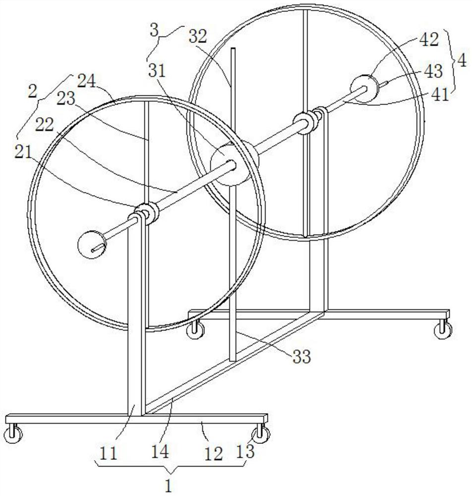
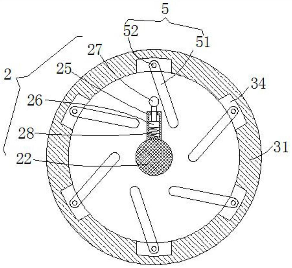
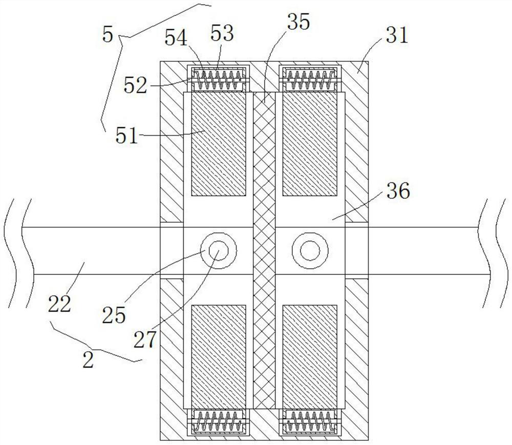
[0022] see Figure 1-3 , the present embodiment provides a wire positioning device for electrical engineering, including a support mechanism 1, two winding mechanisms 2 and a reversing mechanism 3, the two winding mechanisms 2 are symmetrically distributed, and are respectively rotated on the sides of the support mechanism 1 On both sides of the upper end, the two winding mechanisms 2 are connected by the reversing mechanism 3. By setting the two winding mechanisms 2, the cables are respectively wound on the winding mechanisms 2, and the two-way simultaneous pay-off operation can be performed. , increase the speed of pay-off, meet the requirements of cable laying, and save manpower. In addition, when the pay-off is completed, the excess cables released by the inertial rotation can be collected by reversing the reversing mechanism 3 and reversing the winding mechanism 2. Tight operation, at the same time, the winding mechanism 2 can be positioned to prevent the winding mechanis...

Embodiment 2

[0035] see figure 1 , further improvements have been made on the basis of Example 1:

[0036] In order to solve the problem of how to move the overall structure, the bottom ends of the two support columns 11 are horizontally fixed and welded with a support bottom beam 12, and a reinforcing beam 14 is arranged between the two support bottom beams 12 opposite to the middle of the side wall, and the support bottom beam 12 Both sides of the bottom end of the bottom end are provided with brake universal wheels 13, and the support column 11 is supported by the support bottom beam 12, thereby enhancing the support stability of the support column 11, and the overall structure can be assisted to move by the brake universal wheels 13.


PUM


Abstract

The invention discloses an electrical engineering pay-off positioning device, and relates to the technical field of electrical engineering. The electrical engineering pay-off positioning device comprises a supporting mechanism, two wrapping connection mechanisms and a reversing mechanism, the two wrapping connection mechanisms are symmetrically distributed and arranged at the positions of the two sides of the upper end of the supporting mechanism correspondingly, and the two wrapping connection mechanisms are connected through the reversing mechanism. According to the electric engineering pay-off positioning device, pay-off operation can be carried out in two directions at the same time, the pay-off speed is increased, the cable laying requirement is met, and manpower is saved. In addition, after pay-off is finished, redundant cables which are paid off under the inertia effect in a rotating mode can be tightened by reversely stirring the wrapping connection mechanisms through the reversing mechanism, and meanwhile, the situation that due to random rotation pay-off of the wrapping connection mechanisms, excessive pay-off is caused, and waste is caused accordingly can be avoided.

Description

technical field [0001] The invention relates to the technical field of electrical engineering, in particular to an electrical engineering setting-out positioning device. Background technique [0002] In order to connect the circuit during the construction of electrical engineering, the cables will be reasonably arranged to connect the circuit. During the use of the cable, it is often necessary to wind the cable on the ring winding frame in advance, and release the wire according to the use requirements. At present, due to In the construction of multi-circuit lines, the method of one pull and one pay-off is still adopted. It takes a long time to use a single ring-shaped winding frame, which wastes manpower. Under the action of inertia, the winding frame will still automatically unwind the wires and cannot stop in time. It needs to be manually reversed to the ring winding frame to wind up the excess cables. The operation is very inconvenient, so a kind of electrical engineerin...

Claims


Application Information

Patent Timeline
Patent Type & Authority Applications(China)
IPC IPC(8): B65H49/32B65H49/34B65H59/04
CPCB65H49/325B65H49/324B65H49/34B65H59/04Y02W30/82
Inventor 孙文祥邹培林陈诚任涛高亦斌郏进进柏煜刘唯猛
Owner 安徽祥源科技股份有限公司
Why Eureka
Try Eureka