Charging parking space for automobile charging pile
A technology for car charging and parking spaces, which is applied to buildings, roads, and roads where cars are parked. It can solve problems such as insufficient light, collisions, and unskilled driving skills, and achieve the effect of reducing energy consumption.
- Summary
- Abstract
- Description
- Claims
- Application Information
AI Technical Summary
Problems solved by technology
Method used
Image
Examples
Embodiment 1
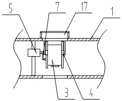
[0021] refer to Figure 1-4 , is a structural schematic diagram of Embodiment 1 of the present invention, a charging parking space for a car charging pile, at least including a parking surface 1, and also includes a pair of prompt parts, a pair of trigger parts, a limit bar 2, a range finder 3, and a turntable 4. The motor 5, the flap 6, the rocker 7 and the control unit 8, a pair of prompting parts are arranged on both sides of the parking surface 1, a pair of the triggering parts are embedded in the two ends of the parking surface 1, and the limit The column 2 is fixed on one end of the parking surface 1, and the middle part of the limit column 2 is located on the side wall of the trigger part, and there is an active opening. The movable opening is hinged with a turret 4, and the rangefinder 3 is detachably connected to the turret 4. , the turning frame 4 is detachably connected to the turning plate 6, the turning plate 6 is located in the movable opening, the motor 5 is det...
Embodiment 2
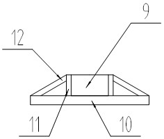
[0025] Referring to Figure 1 and image 3 , the difference of this embodiment is that the prompting part includes an LED light strip 9, a base plate 10, a pair of vertical plates 11 and a pair of reinforcement plates 12, the base plate 10 is fixed on the parking surface 1, and the LED light The strip 9 is bonded to the upper surface of the base plate 10, and a pair of vertical plates 11 are vertically fixed on the base plate 10. The LED light strip 9 is located between the pair of vertical plates 11, and the edges of the vertical plates 11 and the base plate 10 are fixed and strengthened. board 12 , the LED strip 9 is electrically connected with the control unit 8 .
[0026] In actual use: when the vehicle triggers the first trigger part, the LED light strip 9 displays green, the distance is updated in real time through the rangefinder 3, the display length of the LED light strip 9 is changed, and the LED light strip 9 displays after the vehicle travels two-thirds Yellow, at ...
Embodiment 3
[0028] Referring to Fig. 1, the difference of this embodiment is that one of the triggering parts is set at one end of the parking surface 1, and the other of the triggering parts is set at the other end of the parking surface, and the distance from the other end is greater than 60 cm.
[0029] In actual use: According to the size of the parking space, the position of the trigger part of the parking surface can be changed to make the vehicle park in a safe position.
PUM
 Abstract
Description
Claims
Application Information
 - R&D Engineer
- R&D Manager
- IP Professional
- Industry Leading Data Capabilities
- Powerful AI technology
- Patent DNA Extraction
Browse by: Latest US Patents, China's latest patents, Technical Efficacy Thesaurus, Application Domain, Technology Topic, Popular Technical Reports.
© 2024 PatSnap. All rights reserved.Legal|Privacy policy|Modern Slavery Act Transparency Statement|Sitemap|About US| Contact US: help@patsnap.com


