
Monitoring device for highway electromechanical equipment and control system thereof

A technology for monitoring equipment and electromechanical equipment, applied in mechanical equipment, pump control, mining equipment, etc., can solve the problems of incomplete fan monitoring data, inability to monitor multiple locations, and inability to monitor and independently monitor data at each location, etc., to achieve Improve data comprehensiveness, expand coverage, and avoid manual control effects

Active Publication Date: 2021-06-22
SHANDONG HI SPEED COMPANY
View PDF5 Cites 1 Cited by
  • Summary
  • Abstract
  • Description
  • Claims
  • Application Information

AI Technical Summary

Problems solved by technology

[0005] The purpose of the present invention is to provide a monitoring device and its control system for expressway electromechanical equipment in order to solve the above problems, to solve the problem that the monitoring device in the prior art is usually fixed to the fan. When the wind is monitored, the monitoring position is fixed, which leads to the incomplete monitoring data of the monitoring equipment for the fan, and it is impossible to monitor multiple positions of the fan outlet. At the same time, it also has the ability to control the movement through the motor Monitoring device, but the existing monitoring device often adjusts and controls the position movement through the coordinated adjustment of multiple motors, which requires manual control of the monitoring equipment, which cannot achieve the problem of independent monitoring of each position data

Method used


Image

  • Monitoring device for highway electromechanical equipment and control system thereof
  • Monitoring device for highway electromechanical equipment and control system thereof
  • Monitoring device for highway electromechanical equipment and control system thereof

Examples


Embodiment Construction

[0038] Embodiment 1 of the present invention provides a monitoring device for expressway electromechanical equipment.

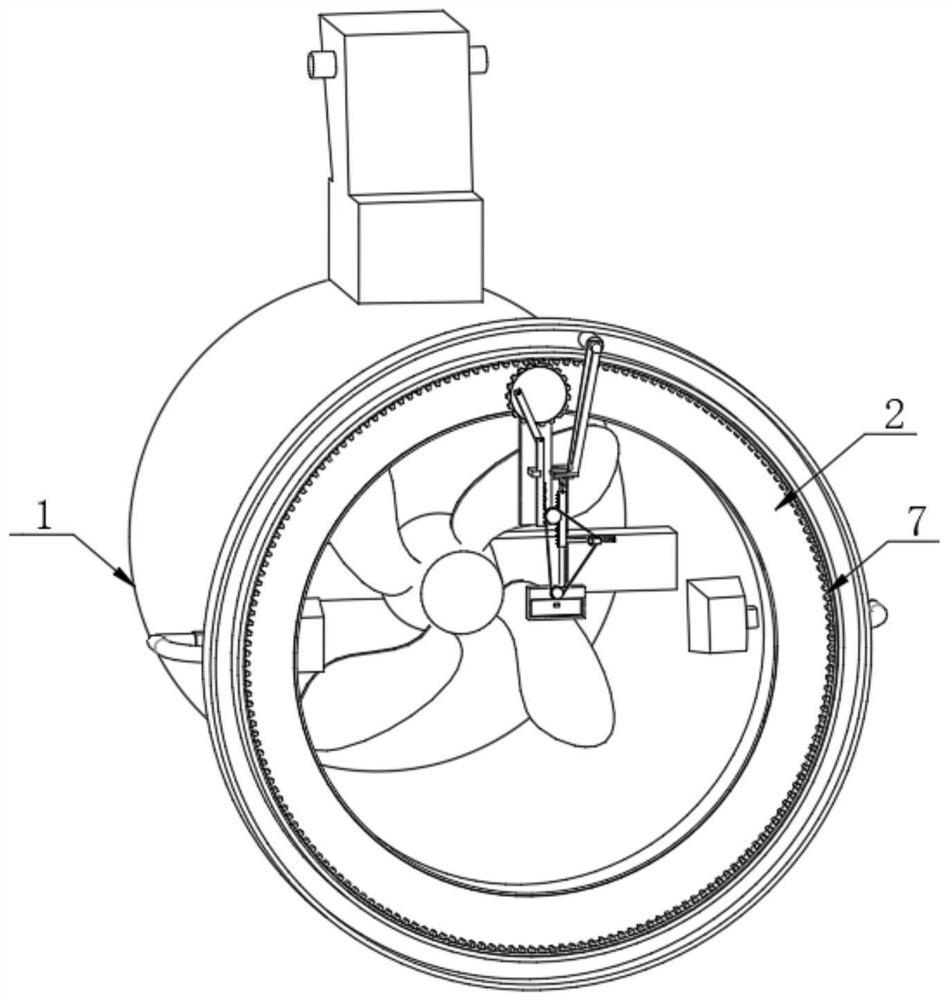
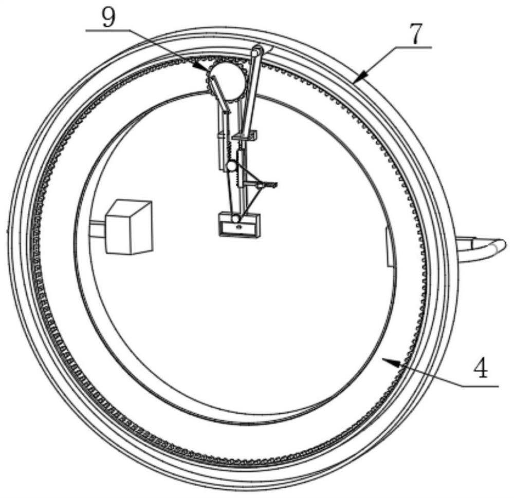
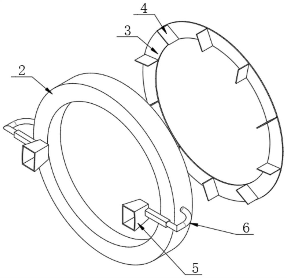
[0039] see figure 1 , figure 2 , image 3 , Figure 4 , Figure 5 , Figure 6 and Figure 7 , comprising a fan device 1, the outer side of the fan device 1 is fixedly connected with an installation frame 2, a groove is opened on one side of the installation frame 2, an adjustment assembly is arranged on one side of the installation frame 2, and a flip assembly is installed on the front side of the adjustment assembly;

[0040] The adjustment assembly includes a rotating plate 3, which is embedded in the groove. The rotating plate 3 is connected to the installation frame 2 in rotation. Both sides are fixedly connected with a connecting pipe 6 for connecting with the installation frame 2, the connecting pipe 6 runs through the outside of the fan device 1 and extends to the inside of the fan device 1, the connecting pipe 6 is fixedly connected with the fa...


PUM


Abstract

The invention provides a monitoring device for highway electromechanical equipment and a control system thereof, and relates to the field of monitoring device. The monitoring device for the highway electromechanical equipment and the control system thereof comprise a fan device, wherein the outer side of the fan device is fixedly connected with a mounting frame, a groove is formed in one side of the mounting frame, an adjusting assembly is arranged on one side of the mounting frame, a turnover assembly is arranged on the front side of the adjusting assembly, the adjusting assembly comprises a rotating plate, and the rotating plate is embedded in the groove. According to the monitoring device for the highway electromechanical equipment, when a gear disc rotates to drive a connecting rod to pull a first rack to move, so that a connecting gear drives a second rack to move under the limiting of a first telescopic rod; and when the second rack moves, a fixing rod is driven to push a placing frame to move downwards, so that the monitoring device can move up and down while detecting the fan device in an all-around mode, the detection coverage range is expanded, and the comprehensiveness of the detected data is improved.

Description

technical field [0001] The invention relates to expressway electromechanical equipment, in particular to a monitoring equipment for expressway electromechanical equipment and a control system thereof, belonging to the technical field of monitoring equipment. Background technique [0002] With the rapid development of highway traffic in our country, a large number of highway tunnels have been built. By the end of 2013, my country's road tunnels had broken through the 10,000 mark. Long road tunnels are generally equipped with mechanical ventilation devices, and more than 95% of them use suspended jet ventilation, so the stability of the suspended jet fan foundation has gradually been highly valued by people. [0003] Since the existing detection equipment is generally fixed, the monitoring position of the monitoring equipment is fixed when monitoring the wind output of the fan, which leads to the incomplete monitoring data of the monitoring equipment on the fan Multiple posi...

Claims


Application Information

Patent Timeline
Patent Type & Authority Applications(China)
IPC IPC(8): F04D27/00F03D9/20E21F1/00E21F17/18
CPCF04D27/001F04D27/008F03D9/20E21F1/003E21F17/18Y02E10/72
Inventor 刘丛赵大鹏许军王树兴孙凌峰谭明磊王建王筱蓉鞠琳张平
Owner SHANDONG HI SPEED COMPANY
Learn More