
Electric fault detection system for vehicle

A technology for fault detection and power consumption faults, applied in the direction of measuring electricity, measuring devices, and measuring electrical variables, etc., can solve problems such as lack of equipment, hidden dangers of equipment failures that cannot be found in time for regular maintenance, and data that needs to be stored and processed, so as to improve comprehensiveness, The effect of preventing electrical fire hazards

Active Publication Date: 2016-06-22
单立辉
View PDF9 Cites 22 Cited by
  • Summary
  • Abstract
  • Description
  • Claims
  • Application Information

AI Technical Summary

Problems solved by technology

[0004] For a long time, my country's automobile equipment has implemented a regular maintenance system, but regular maintenance cannot find hidden troubles inside the equipment in time; the current automotive equipment maintenance system is developing in the direction of state-of-the-art maintenance
Some new online fault monitoring technologies have been widely used at home and abroad, but currently there is a lack of online monitoring devices and technologies for hidden dangers in the very early and mid-early stages; fault recording technology is currently a widely used electrical online fault monitoring technology It reflects the fault condition by real-time detection and recording of time-varying transient parameters such as current and voltage, and the waveform diagram composed of actual sampling points during the fault period
However, fault recording needs to store a large amount of data. At the same time, the value of electrical abnormal parameters is generally much smaller than the fault setting value. Outside the scope of fault recording monitoring, expanding to abnormal recording will cause more massive data to be stored and processed. This is obvious. Not an advantage for embedded microcontroller systems

Method used


Image

  • Electric fault detection system for vehicle

Examples


Embodiment 1

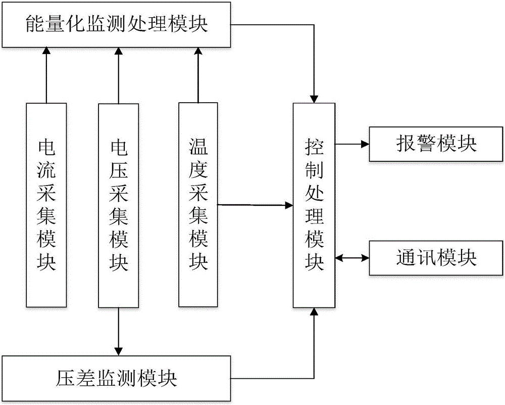
[0023] refer to figure 1 , a vehicle electrical fault detection system proposed in this embodiment is used to detect the power-on working status of the internal power supply module and each power consumption module of the vehicle. The automotive electrical fault detection system includes: a voltage acquisition module, a current acquisition module, a temperature acquisition module, an energy monitoring and processing module, a differential pressure monitoring module, a control processing module, a communication module and an alarm module.

[0024] The voltage acquisition module is connected with the power supply module and each power consumption module, and is used to detect the output voltage of the power supply module and the working voltage of each power consumption module respectively.

[0025] The current collecting module is connected with the power module and each power consumption module, and is used for collecting the output current and residual current of the power mo...


PUM


Abstract

The invention discloses an electric fault detections system for a vehicle, and the system comprises a voltage collection module, a current collection module, a temperature collection module, an energy monitoring and processing module, a voltage difference monitoring module, a control processing module, a communication module, and an alarm module. For a power module and all power consumption modules, the system firstly obtains the product of current and voltage; secondly carries out the integration of the product of current and voltage in a set time period, and obtains the electric energy or reference electric energy; thirdly monitors the power utilization and hidden conditions of the power module and all power consumption modules through the electric energy or reference electric energy in all time periods. According to the invention, the system carries out the multiplication of the current and voltage signals to generate power, and then carries out the time integration of the power, i.e., carrying out the amplification and judgment of small current and voltage signals and weak hidden trouble signals, thereby facilitating the guaranteeing of the monitoring depth of early hidden troubles, and avoiding a condition that a small fault cannot be inspected. The system can achieve the earlier finding of faults and hidden troubles, and guarnatees the safer power utilization of the vehicle.

Description

technical field [0001] The invention relates to the technical field of automobile safety monitoring, in particular to an automobile electric fault detection system. Background technique [0002] Automobiles are widely used as a means of transportation, and people's requirements for their safety are becoming more and more stringent. At present, with the development of electric power applications, the proportion of pure electric vehicles, electric hybrid vehicles, and electric oil hybrid vehicles in automobiles is increasing. In short, electric power is more and more widely used in the automotive field. Therefore, automobile safety Monitoring should also pay attention to the detection of electrical parameters of the vehicle power system. [0003] In today's many electrical testing processes, some important electrical fault parameters are difficult to measure directly with existing instruments, and the state characteristics of some electrical parameters are very different betw...

Claims


Application Information

Patent Timeline
IPC IPC(8): G01R31/00
CPCG01R31/006
Inventor 单立辉
Owner 单立辉
Learn More