
Speed change mechanism for achieving automatic gear shifting through output speed and vehicle

A technology of automatic gear shifting and transmission mechanism, which is applied in the direction of automatic clutch, mechanical equipment, transmission device, etc. It can solve problems affecting riding experience, transmission mechanism failure, and affecting service life, so as to improve riding experience, ensure reset, The effect of prolonging the service life

Pending Publication Date: 2021-06-22
BAFANG ELECTRIC (SUZHOU) CO LTD
View PDF1 Cites 9 Cited by
  • Summary
  • Abstract
  • Description
  • Claims
  • Application Information

AI Technical Summary

Problems solved by technology

In this case, the automatic downshift of the transmission mechanism will affect the riding experience, and the increase in shift frequency will easily lead to the failure of the transmission mechanism and affect its service life

Method used


Image

  • Speed change mechanism for achieving automatic gear shifting through output speed and vehicle
  • Speed change mechanism for achieving automatic gear shifting through output speed and vehicle
  • Speed change mechanism for achieving automatic gear shifting through output speed and vehicle

Examples


Embodiment

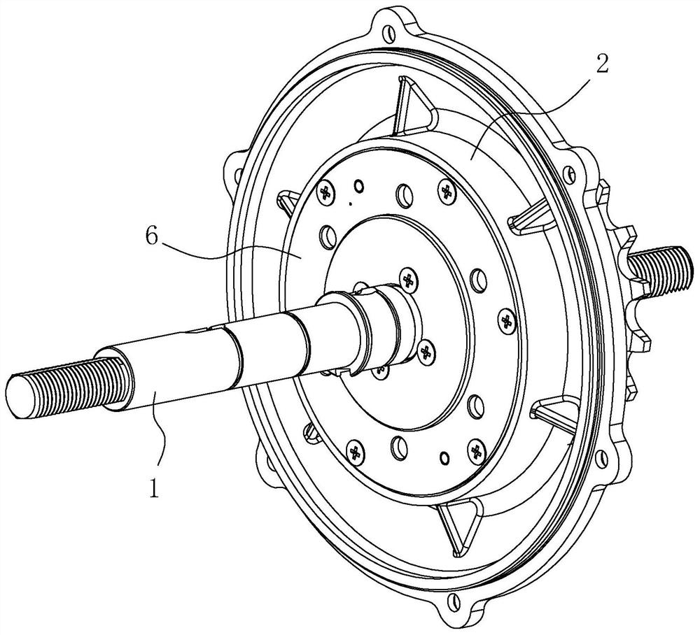
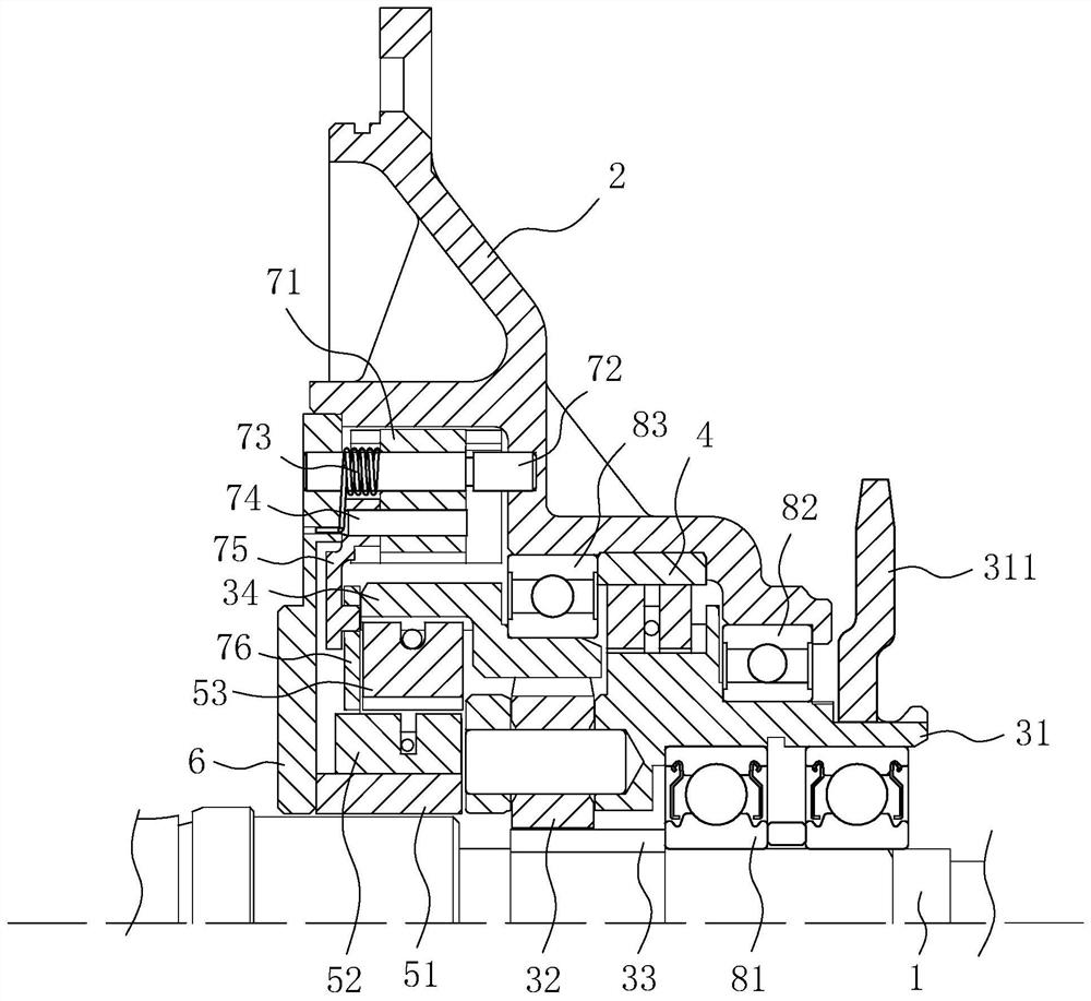
[0037] A speed change mechanism that uses output speed to realize automatic shifting, refer to figure 1 and figure 2 , which includes a power output unit and a power output unit; the power input unit includes a first input member and a second input member, and the rotation speed of the second input member is higher than that of the first input member; between the first input member and the power output unit A first clutch assembly is provided, a second clutch assembly is provided between the second input member and the power output unit, and the power output unit is provided with a centrifugal drive assembly for controlling the second clutch assembly; wherein, the speed of the power output unit is lower than When the value is set, the centrifugal drive assembly restricts the second clutch assembly, so that the speed of the second input cannot be transmitted to the power output unit through the second clutch assembly. At this time, the speed of the first input is transmitted t...

Embodiment 2

[0051] A vehicle including the transmission mechanism in Embodiment 1.

[0052] The vehicle in this embodiment may be a bicycle, an electric power-assisted bicycle or other vehicles that need to change speed.


PUM


Abstract

The invention discloses a speed change mechanism for achieving automatic gear shifting through the output speed and a vehicle, and relates to the field of speed change devices. According to the technical scheme, the speed change mechanism comprises a power output unit, a power input unit and a second clutch assembly; the power input unit comprises a first input part and a second input part, and the rotating speed of the second input part is larger than that of the first input part; and the power output unit is provided with a centrifugal driving assembly used for controlling the second clutch assembly. When the rotating speed of the power output unit is smaller than a set value, the centrifugal driving assembly limits the second clutch assembly so that the rotating speed of the second input part cannot be transmitted to the power output unit through the second clutch assembly; and after the rotating speed of the power output unit reaches the set value, the centrifugal driving assembly releases the second clutch assembly so that the rotating speed of the second input part can be transmitted to the power output unit through the second clutch assembly. Automatic gear shifting is achieved through the output speed, the riding experience can be improved, the gear shifting frequency is reduced, and the service life is prolonged.

Description

technical field [0001] The invention relates to the field of speed change devices, more specifically, it relates to a speed change mechanism and a vehicle which utilize output speed to realize automatic gear shifting. Background technique [0002] The general internal speed change mechanism uses centrifugal force to realize automatic speed change. When a certain cadence speed is reached, the centrifugal block is thrown away to realize automatic upshifting. When the cadence speed drops below the speed change point, the centrifugal block will shrink to realize automatic downshifting. For example, it is shown in the Chinese patent whose authorized announcement number is CN208882034U. [0003] However, for the vehicle using the above-mentioned speed change mechanism, when the vehicle is running at high speed (greater than the speed change point), if the rider does not want to step on it, or does not need to step on the downhill, the speed change mechanism will automatically redu...

Claims


Application Information

Patent Timeline
Patent Type & Authority Applications(China)
IPC IPC(8): F16H3/70F16H3/74F16D43/16
CPCF16H3/70F16H3/74F16D43/16F16D2043/145F16H2003/447
Inventor 王清华王英喆邹斌黄善劲张苏北
Owner BAFANG ELECTRIC (SUZHOU) CO LTD
Learn More