Cleaning system
A cleaning system and cleaning equipment technology, applied in the field of cleaning systems, can solve the problems of restricting the autonomous cleaning time of the sweeping robot and increasing the number of human interventions.
- Summary
- Abstract
- Description
- Claims
- Application Information
AI Technical Summary
Problems solved by technology
Method used
Image
Examples
no. 1 approach
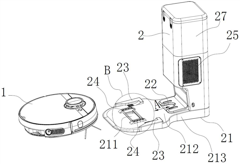
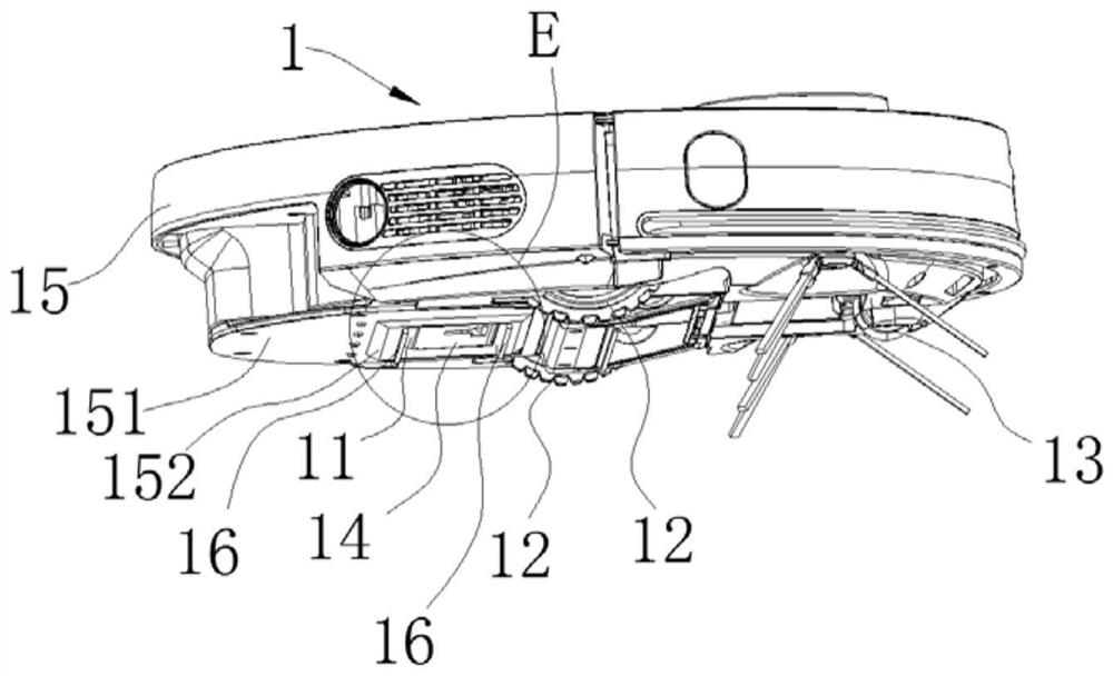
[0130] In an embodiment of this application, please refer to Figure 9 and Figure 10 , the first drive mechanism includes a transmission component and a motor 41 . The motor 41 has a motor shaft, the transmission part is connected to the motor shaft in rotation, the opposite ends of the cover plate 14 are configured with a rotating shaft connected to the dust box 11 in rotation, the driven mechanism is fixedly connected to the rotating shaft, and the transmission part and the driven mechanism are driven to cooperate to drive The rotating shaft drives the cover plate 14 to rotate. In such a structure, the motor 41 drives the transmission part to rotate through the motor shaft, and the rotating transmission part drives the driven mechanism to rotate, and the driven mechanism drives the rotating shaft to rotate and then drives the cover plate 14 to rotate, so that the cover plate 14 rotates to the position where the dust discharge port is opened. Thereby, the dust discharge po...
no. 2 approach
[0140] In an embodiment of this application, please refer to Figure 11-Figure 14 , the first driving mechanism includes a first electromagnet 43, the first electromagnet 43 is arranged on the carrying device 21, and the driven mechanism includes a first magnetic member 32; when the dust discharge port 111 needs to be opened, the first electromagnet 43 is in a power-on state , the first magnetic member 32 and the first electromagnet 43 generate a magnetic force to drive the cover plate 14 to rotate to the position where the dust outlet 111 is opened. With such a structure, when the dust outlet 111 needs to be opened, the first electromagnet 43 is energized, and the cover plate 14 is driven to rotate by the magnetic force generated by the first magnetic force member 32 and the first electromagnet 43, so that the cover plate 14 overcomes the force of the reset member 17. Active force turns to the position of opening the dust discharge port 111, thereby opening the dust discharge...
no. 3 example
[0153] In the third embodiment of this application, please refer to Figure 15-Figure 20, the driven mechanism includes a hooking portion 34 disposed on the bottom side of the cover plate 14 , and the hooking portion 34 has an opening slot 3411 and a first notch 3412 communicating with the opening slot. The first driving mechanism includes a hook 46 and a reset mechanism 48 . The first end of the hook 46 is rotatably connected to the carrying device 21; when the self-cleaning device 1 passes the dust collection suction port 211 in the direction close to the dust collection station 2, the second end of the hook 46 is inserted into the opening through the first notch 3412 In the groove 3411, the drive hook 34 drives the cover plate 14 to rotate to the position of opening the dust outlet 111; during the movement of the self-cleaning device 1 along the direction away from the dust collection station 2, the second end of the hook 46 passes through the first notch 3412 disengages f...
PUM
 Abstract
Description
Claims
Application Information
 - R&D
- Intellectual Property
- Life Sciences
- Materials
- Tech Scout
- Unparalleled Data Quality
- Higher Quality Content
- 60% Fewer Hallucinations
Browse by: Latest US Patents, China's latest patents, Technical Efficacy Thesaurus, Application Domain, Technology Topic, Popular Technical Reports.
© 2025 PatSnap. All rights reserved.Legal|Privacy policy|Modern Slavery Act Transparency Statement|Sitemap|About US| Contact US: help@patsnap.com


