A kind of brushing equipment for quick-setting thermal insulation paint on the surface of crucible

A technology of thermal insulation paint and crucible, which is applied to the device and coating of the surface coating liquid, which can solve the problems of time-consuming manual operation, uneven painting, low efficiency, etc., and achieve the effect of protecting the crucible

Active Publication Date: 2022-05-03
湖南展鹰科技有限公司
View PDF8 Cites 0 Cited by
  • Summary
  • Abstract
  • Description
  • Claims
  • Application Information

AI Technical Summary

Problems solved by technology

[0004] In order to overcome the shortcomings of manual painting, uneven painting, waste of resources, time-consuming and labor-intensive manual operation, and low efficiency, the technical problem of the present invention is to provide a quick-setting crucible surface that can achieve uniform smearing, save time and effort, and have high efficiency. Insulation paint surface brushing equipment

Method used


Image

  • A kind of brushing equipment for quick-setting thermal insulation paint on the surface of crucible
  • A kind of brushing equipment for quick-setting thermal insulation paint on the surface of crucible
  • A kind of brushing equipment for quick-setting thermal insulation paint on the surface of crucible

Examples


Embodiment 1

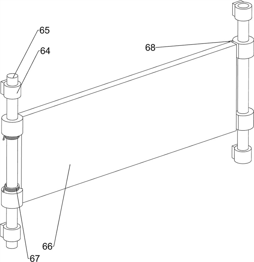
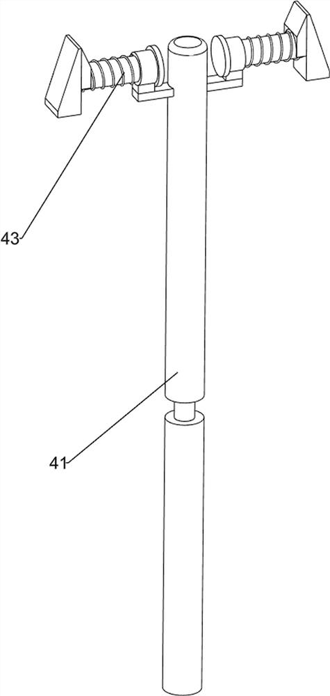
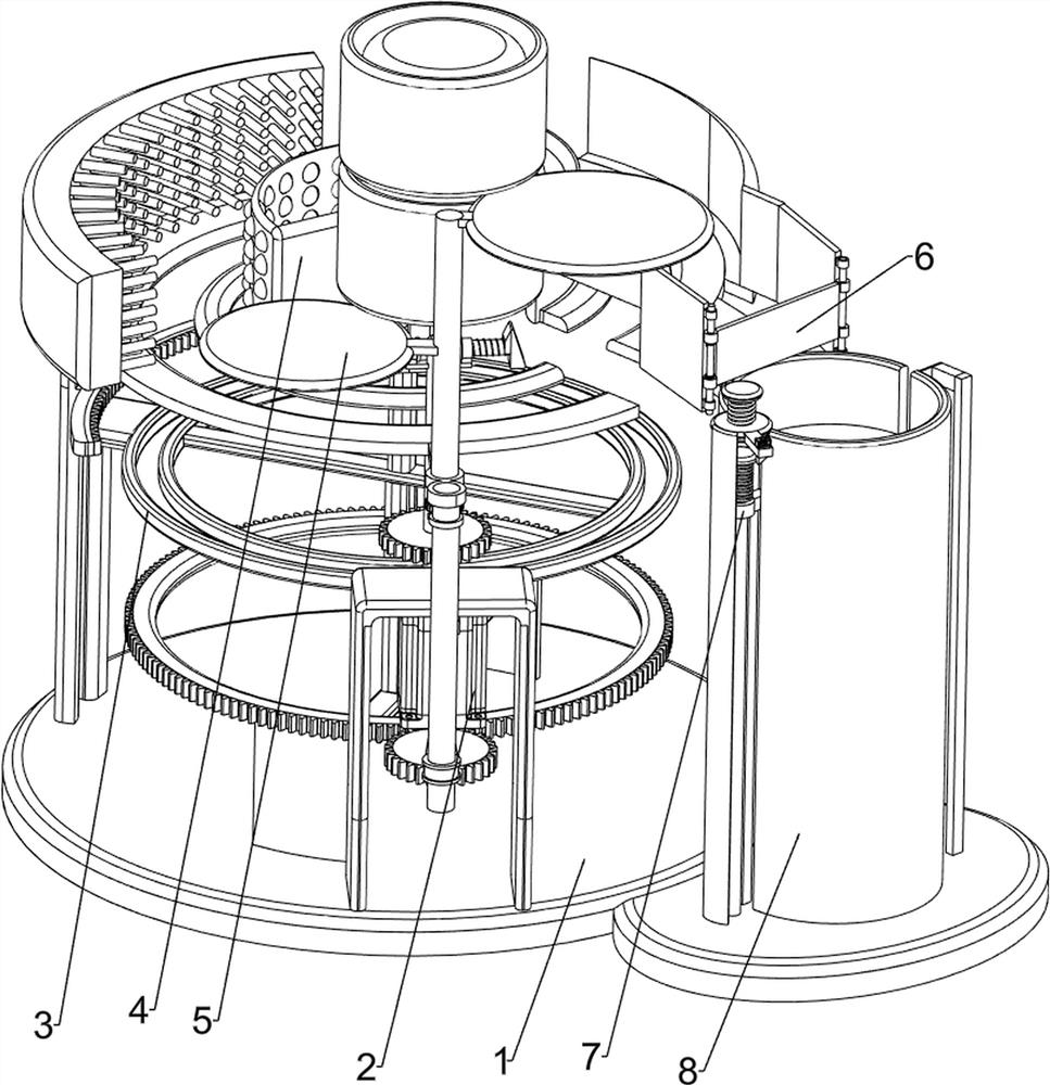
[0070] A kind of crucible surface fast-setting thermal insulation paint surface brushing equipment, such as Figure 1-4 As shown, it includes a base plate 1, a motor 2, a rotating mechanism 3 and a paint brushing mechanism 4. The front side of the base plate 1 is provided with a motor 2, and the output shaft of the motor 2 is connected with full gears. The base plate 1 is connected with a rotating mechanism 3, and the rotating mechanism 3 There is a painting mechanism 4 on it.

[0071]The rotating mechanism 3 includes a first support column 31, a first ring rack 32, a first support frame 33, a second support column 34, a third support column 35, a first slide rail 36 and a second slide rail 37, and the bottom plate 1 The front and rear sides are connected with first support columns 31, a first support frame 33 is arranged between the first support columns 31, and a first ring rack 32 is rotatably connected between the tops of the first support columns 31, and the left side of ...

Embodiment 2

[0075] On the basis of Example 1, such as Figure 5-10 As shown, also includes a feeding device 5, the feeding device 5 includes a second support frame 51, a second rotating shaft 52, a conveyor belt 53, a third rotating shaft 54, a material blocking plate 55, a missing gear 56, a second spur gear 57 , the third support frame 58 and the second receiving frame 59, the second slide rail 37 right front side is provided with the second support frame 51, the front side of the second support frame 51 is rotatably connected with the second rotating shaft 52, the second rotating shaft 52 and A conveyor belt 53 is connected between the output shafts of the motor 2, and a third rotating shaft 54 ​​is rotationally connected on the second rotating shaft 52. The bottom of the third rotating shaft 54 ​​is provided with a second spur gear 57, and the top of the second rotating shaft 52 is provided with a missing gear 56. Gear 56 meshes with the second spur gear 57, and the middle and upper p...


PUM


Abstract

The invention relates to a brush coating device, in particular to a brush coating device for a fast-setting thermal insulation paint surface on the surface of a crucible. The technical problem of the present invention is to provide a quick-setting thermal insulation paint coating equipment on the crucible surface that can achieve uniform coating, save time and effort, and have high efficiency. The technical solution is: a brushing equipment for fast-setting thermal insulation paint on the surface of a crucible, including a base plate and a motor, a motor is provided on one side of the base plate, and the output shaft of the motor is connected to a full gear; a rotating mechanism is connected to the base plate; Mechanism, the rotating mechanism is provided with a painting mechanism. Through the cooperation between the feeding device, the rotating mechanism and the painting mechanism, automatic interval feeding and automatic brushing of the crucible with thermal insulation paint can be realized, which saves time and effort.

Description

technical field [0001] The invention relates to a brush coating device, in particular to a brush coating device for a fast-setting thermal insulation paint surface on the surface of a crucible. Background technique [0002] In the process of making the crucible, it is necessary to brush the surface of the crucible with thermal insulation paint, which can have the effect of thermal insulation on the crucible. Now when brushing the thermal insulation paint, usually manually use a brush to spray the thermal insulation paint on the outer wall of the crucible. Manual painting will cause some damage. Disadvantages, first, uneven painting will reduce the value of the product itself; second, it will cause the thermal insulation paint to drip everywhere, wasting resources; third, manual operation is time-consuming and laborious, and the efficiency is low. [0003] In order to be able to solve the above problems, a fast-setting thermal insulation paint brushing equipment on the surfac...

Claims


Application Information

Patent Timeline
Patent Type & Authority Patents(China)
IPC IPC(8): B05C1/02B05C11/02B05C13/02
CPCB05C1/022B05C13/02B05C11/023
Inventor 武浩
Owner 湖南展鹰科技有限公司
Why Eureka
Try Eureka