

Punching device for intelligently manufacturing motor rotor iron core
A technology of rotor core and punching device, which is applied in the manufacture of stator/rotor body, feeding device, positioning device, etc., which can solve the problems of increasing the risk of operation, being unfavorable for transportation and post-processing, and occupying a large space
- Summary
- Abstract
- Description
- Claims
- Application Information
AI Technical Summary
Problems solved by technology
Method used
Image

Examples
Embodiment 1
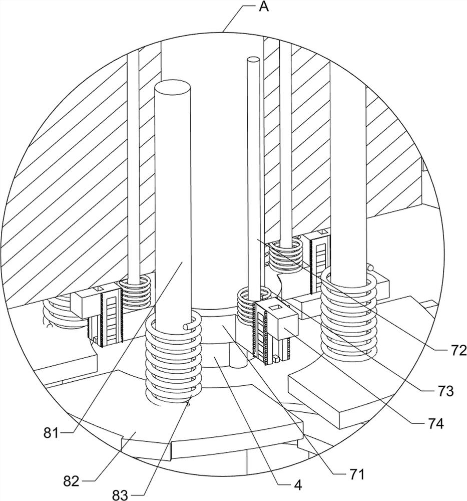
[0027] A punching device for motor rotor cores for intelligent manufacturing, such as Figure 1-4 As shown, it includes a support frame 1, a frame 2, a first connecting block 21, a cylinder 3, a stamping die 4, a support plate 5, a stamping pad 6, a pressing assembly 7 and a stamping assembly 8, and the bottom three of the frame 2 Both sides are equipped with a support frame 1, the top of the frame 2 is provided with a first connecting block 21, the upper part of the first connecting block 21 is provided with a cylinder 3, the bottom of the telescopic rod of the cylinder 3 is provided with a stamping die 4, and the upper part of the frame 2 is provided with a support The plate 5 and the support plate 5 are placed with a stamping block 6 , a primary pressing assembly 7 is connected between the stamping die 4 and the first connecting block 21 , and a stamping assembly 8 is arranged between the stamping die 4 and the first connecting block 21 .
[0028] The primary compression as...
Embodiment 2
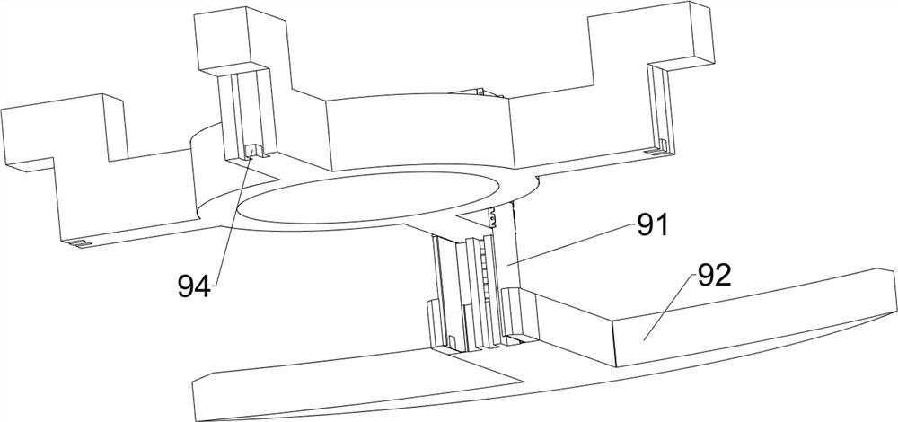
[0032] On the basis of Example 1, such as Figure 5-9 As shown, a secondary pressing assembly 9 is also included, and the secondary pressing assembly 9 includes a guide sleeve 91, a T-shaped block 92, a third spring 93 and a second limit block 94, and the bottom of the L-shaped guide block 74 is provided with There is a third spring 93, the bottom of the third spring 93 is provided with a T-shaped block 92, the top of the T-shaped block 92 is provided with two guide sleeves 91, and the two guide sleeves 91 are slidably connected with the L-shaped guide block 74. Second limiting blocks 94 are provided on four sides of the collar 71 .
[0033] When the L-shaped guide block 74 and the second limit block 94 move downward, the third spring 93 is compressed, so that the guide sleeve 91 and the T-shaped block 92 move downward, and the T-shaped block 92 clamps and fixes the material. The L-shaped guide block 74 and the second limit block 94 move upwards and reset, and the third sprin...
PUM
 Abstract
Description
Claims
Application Information