Stamping device with die inner side pushing and bending structure

A technology of stamping device and die base, which is applied in the field of stamping dies, can solve the problems of affecting the feeding of the material belt and the lifting of the mold material belt, so as to achieve the effect of rapid material removal and improvement of production efficiency

Pending Publication Date: 2021-06-25
SHENZHEN EVA PRECISION TECH GRP CO LTD
View PDF0 Cites 0 Cited by
  • Summary
  • Abstract
  • Description
  • Claims
  • Application Information

AI Technical Summary

Problems solved by technology

[0003] In view of this, the present invention provides a stamping device with a push-bending structure inside the mold, which can effective

Method used


Image

  • Stamping device with die inner side pushing and bending structure
  • Stamping device with die inner side pushing and bending structure
  • Stamping device with die inner side pushing and bending structure

Examples


Embodiment 1

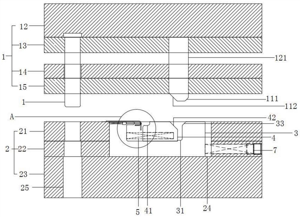
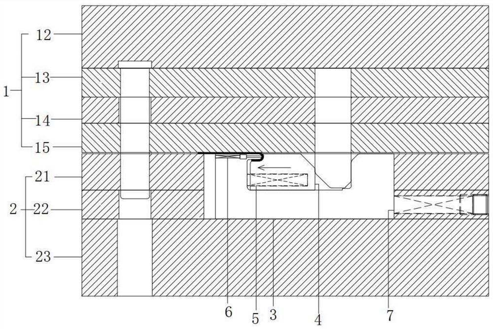
[0024] see Figure 1 to Figure 3 , the figure shows a stamping device with a mold-inside push-bending structure provided by Embodiment 1 of the present invention, which mainly includes:

[0025] The upper die mechanism 1, the upper die mechanism 1 also includes an upper die base 12, an upper splint 13, a stop plate 14 and an upper stripping plate 15, the upper splint 13 is fixedly installed on the upper die base 12, and the stop plate 14 is arranged on the upper splint Below 13, the upper stripping plate is fixedly installed on the stop plate 14, and the stop plate and the stripping plate are fixed with screws to form the unloading part. The upper die mechanism 1 is provided with a punch 11, and the bottom of the punch 11 has a first a slope 111 and a second slope 112;

[0026] Lower mold mechanism 2, lower mold mechanism 2 also comprises lower formwork 21, lower backing plate 22 and lower mold base 23, lower backing plate 22 is fixedly connected on the lower mold base 23, lo...

Embodiment 2

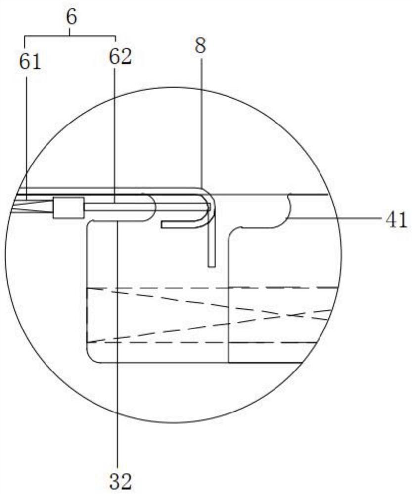
[0033] see Figure 1 to Figure 3 , the figure shows a stamping device with a mold-inside push-bending structure provided by Embodiment 2 of the present invention. On the basis of the above-mentioned embodiments, this embodiment further makes the following technical solutions as improvements: the first A slide block 3 is provided with an installation cavity, and the thimble assembly 6 is arranged in the installation cavity. The thimble assembly 6 includes a third elastic member 61 and a thimble 62. One end of the third elastic member 61 is connected to the cavity wall of the installation cavity. The third elastic The other end of the component 61 is connected to a thimble 62 , and the protruding corner 32 has a through hole for the thimble to enter and exit. Through the setting of the above structure, rapid material removal can be realized and the production efficiency can be improved.

Embodiment 3

[0035] see Figure 1 to Figure 3 , the figure shows a stamping device with a mold-inside push-bending structure provided by Embodiment 3 of the present invention. This embodiment further makes the following technical solutions as improvements on the basis of the above-mentioned embodiments: The mold base 12 is provided with an inner guide post 121 , and the lower die mechanism 2 is provided with a guide hole 25 matching the inner guide post 121 . Through the setting of the above structure, the precision of mold clamping can be improved, and the quality of product production can be improved.


PUM


Abstract

The invention provides a stamping device with a die inner side pushing and bending structure. The stamping device comprises: an upper die mechanism, wherein a punch pin is disposed on the upper die mechanism, and a first inclined face and a second inclined face are disposed at the bottom of the punch pin; and a lower die mechanism, wherein a first mounting groove is formed in the lower die mechanism, a first sliding block is arranged in the first mounting groove, one end of the first sliding block is connected into the first mounting groove through a first elastic component, a second mounting groove is formed in the first sliding block, a second sliding block is arranged in the second mounting groove, the second sliding block is connected to the first sliding block through a second elastic component, one end of the first sliding block is provided with a convex corner used for folding a negative angle, an ejector pin assembly is arranged in the convex corner, the other end of the first sliding block is provided with a third inclined face matched with the first inclined face, one end of the second sliding block is provided with a concave cavity matched with the convex corner, and the other end of the second sliding block is provided with a fourth inclined face matched with the second inclined face. Compared with the prior art, the problem that the material belt feeding is affected due to the fact that a material belt of a die floats too high can be effectively solved.

Description

technical field [0001] The invention relates to the field of stamping dies, in particular to a stamping device with a push-bending structure inside the die. Background technique [0002] In precision and high-precision stamping dies, there will be a lot of inner buckle bends, and the slope slider is usually used to form and strip the material. Often, the lower mold product must follow the slope slider to rise to a certain height before it can be stripped, such as When the depth of the inner buckle is too deep, the lower mold material belt and the slope slider will also float very high. Although this can remove the material smoothly, it affects the feeding of the follow-up material belt. Contents of the invention [0003] In view of this, the present invention provides a stamping device with a push-bending structure inside the mold, which can effectively solve the problem that the material belt of the mold is too high and affects the feeding of the material belt compared w...

Claims


Application Information

Patent Timeline
IPC IPC(8): B21D37/12B21D45/02
CPCB21D37/12B21D45/02
Inventor 张耀华张永明曾文伟林浩鑫
Owner SHENZHEN EVA PRECISION TECH GRP CO LTD
Why Eureka
Try Eureka