Sleeve insulating lead quick wire stripper

An insulated wire, sleeve type technology, used in cable installation devices, electrical components, equipment for dismantling/armored cables, etc. Economic benefits and promotion value, the effect of reducing peeling strength, time-saving and safe peeling

Active Publication Date: 2018-09-04
XIAMEN ELECTRIC POWER SUPPLY COMPANY OF STATE GRID FUJIAN ELECTRIC POWER +1
View PDF9 Cites 0 Cited by
  • Summary
  • Abstract
  • Description
  • Claims
  • Application Information

AI Technical Summary

Problems solved by technology

These tools have disadvantages such as unsafe, cumbersome and time-consuming operation, high price, and heavy tool weight.
[0003] The technical problem solved by the present invention is to provide a tool for quickly stripping the insulation layer of insulated wires in the distribution network, which can solve the problems of easy scratching of hands, long stripping time, complicated tools, and personnel problems when stripping wires in the current stripping method Problems such as high peeling strength
[0005] These wire stripping methods mainly have the following disadvantages: (1) The material performance of domestic wire strippers is not good, and the blades are mostly made of general silicon steel sheets, which are relatively brittle
It is easy to break when too much force is applied
The plastic on the handshake is made of hard plastic and breaks easily
No scaled display to quantify how deep the blade penetrates the insulation
(2) Use the electrician's knife to strip the wires only by hand feel and experience, and the operation process is rough
When stripping the wire, the depth of the knife edge entering the insulation l

Method used


Image

  • Sleeve insulating lead quick wire stripper
  • Sleeve insulating lead quick wire stripper
  • Sleeve insulating lead quick wire stripper

Examples


Embodiment Construction

[0022] The present invention will be further described below in conjunction with the accompanying drawings and embodiments.

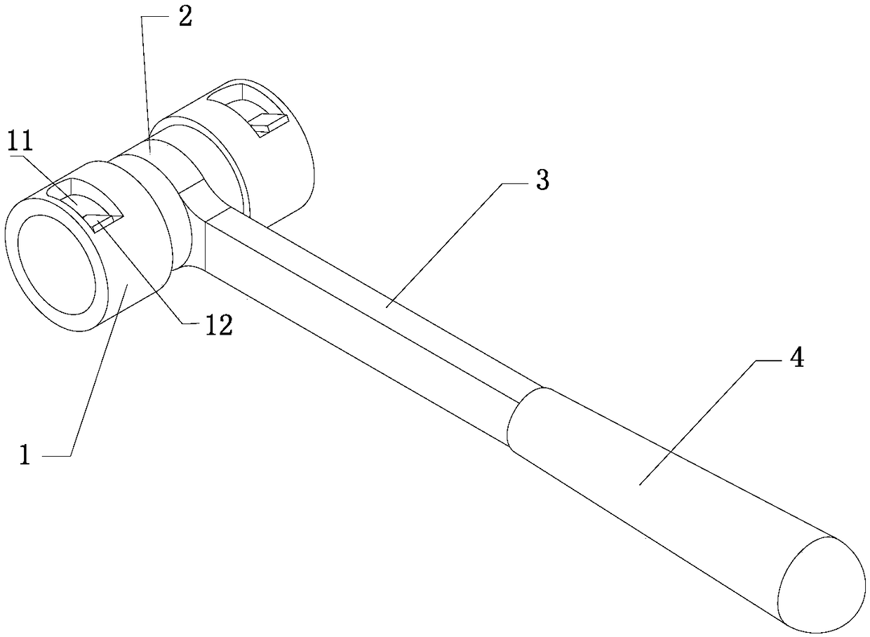
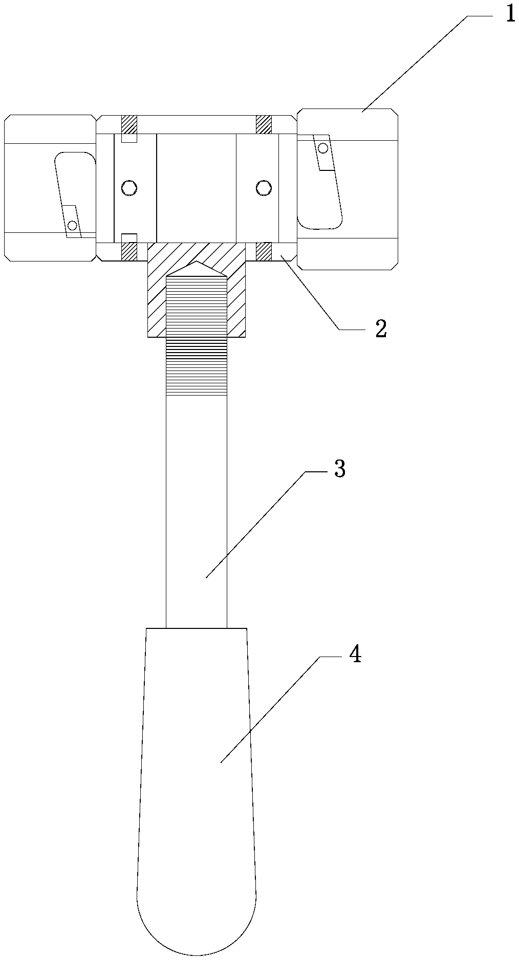
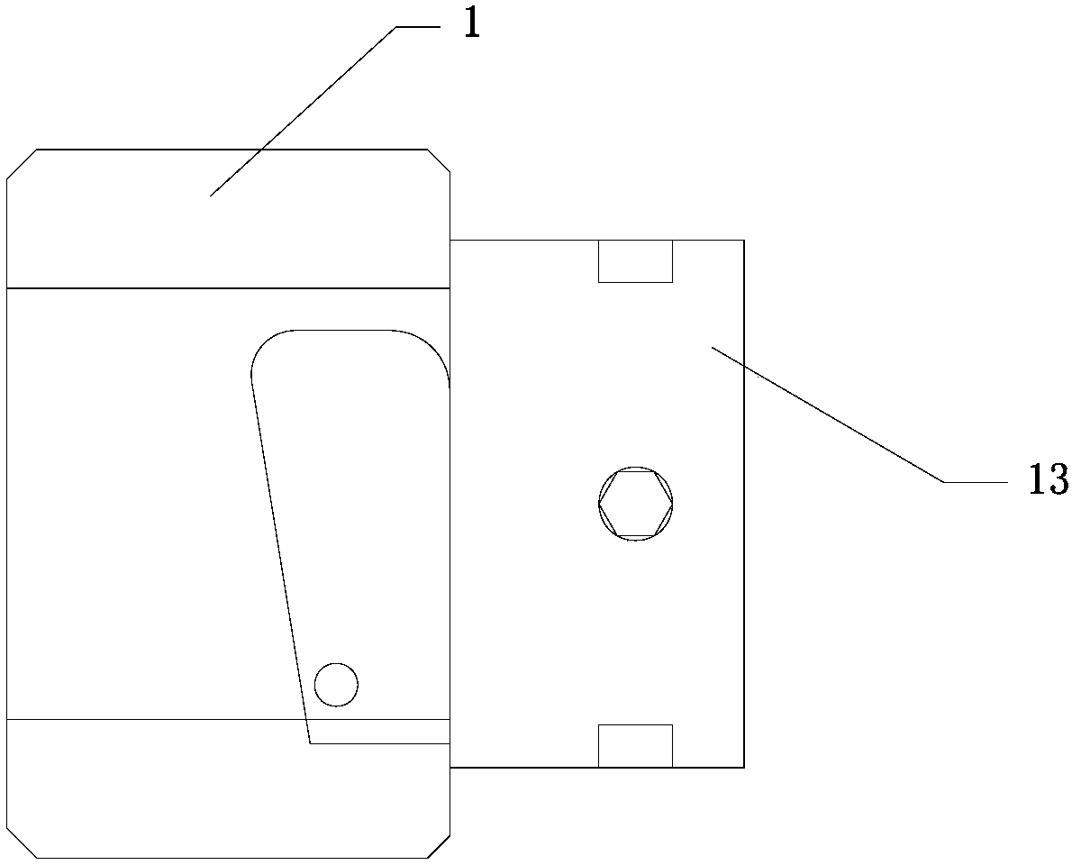
[0023] refer to Figure 1-4 , a sleeve-type insulated wire quick stripper, comprising: two sleeve-type stripping heads 1, a connecting female sleeve 2, an extension rod 3, and a handle 4;

[0024] The two sleeve-type stripping heads 1 are respectively arranged on the two ends of the connecting female sleeve 2 along the length direction, and form a detachable connection with the connecting female sleeve 2; There is a cavity along the length direction of the cavity, and one end of the two cavities away from each other is an open end; the side wall of the cavity has an opening 11 communicating with the cavity and the outside world, and the opening 11 is along the circumferential end of the side wall Connect a sloped inner wall 12; the sloped inner wall 12 extends circumferentially along the side wall and is inclined toward the inside of the cavity; a thre...


PUM


Abstract

The invention provides a sleeve insulating lead quick wire stripper. Two sleeve stripping heads are respectively arranged on the two ends of a connecting mother sleeve along the length direction and form detachable connection with the connecting mother sleeve. Each sleeve stripping head is provided with a cavity along its length direction. The ends away from each other of the two cavities are openends. The side walls of the cavities are provided with openings enabling the cavities and the outside to be communicated. An inclined internal wall is connected on one end of each opening along the circumferential direction of the side wall. The inclined internal wall extends along the circumferential direction of the side wall and includes towards the inside of the cavity. The inclined internalwall is provided with a threaded hole on which a blade is fixed. The blades in the two cavities are different in the depth into the cavities. The side wall of the connecting mother sleeve is providedwith a connecting hole extending along its width direction. A connecting rod is connected with the connecting hole. A handheld handle is arranged on one side, which is away from the connecting hole, of the connecting rod. According to the wire stripper, the insulating layer of the lead can be stripped and the insulating layers of different thickness in the leads of the unified specification can bestripped.

Description

technical field [0001] The invention relates to the field of electric construction tools, in particular to a wire stripper. . Background technique [0002] At present, with the advancement of my country's distribution network reconstruction project, outdoor overhead bare conductors are gradually replaced by overhead insulated conductors, and the utilization rate of insulated conductors is getting higher and higher. How to quickly and safely strip the insulation layer of insulated conductors is a problem that power supply enterprises need to solve one of the technical problems. At present, the tools for stripping the insulation layer mainly include electrician's knife, wire stripper with adjustable knife edge, and some special instruments imported from abroad. These tools have disadvantages such as unsafe, cumbersome and time-consuming operations, high prices, and heavy tools. [0003] The technical problem solved by the present invention is to provide a tool for quickly st...

Claims


Application Information

Patent Timeline
IPC IPC(8): H02G1/12
CPCH02G1/1212
Inventor 廖志华蔡家祥冯祥勋许木成陈宇宏蔡晓军蔡俊宇李迎潘小山张世国曾艺红杨帆
Owner XIAMEN ELECTRIC POWER SUPPLY COMPANY OF STATE GRID FUJIAN ELECTRIC POWER
Why Eureka
Try Eureka