Interface inclusion reinforced thermoplastic composite material ultrasonic welding method

A technology of ultrasonic welding and composite materials, which is applied in the field of ultrasonic welding of thermoplastic composite materials reinforced by interfacial inclusions, can solve the problems of low peel strength, low tensile/peel strength, and low strength of resin matrix, and achieve improved peel strength, Effect of improving tensile/peel strength

Pending Publication Date: 2021-06-11
XI AN JIAOTONG UNIV
View PDF5 Cites 3 Cited by
  • Summary
  • Abstract
  • Description
  • Claims
  • Application Information

AI Technical Summary

Problems solved by technology

[0002] The stiffness and shear strength of ultrasonic spot welded joints are almost equal to or higher than those of mechanically fastened joints, but due to the low tensile/peel strength of ultrasonically welded thermoplastic composite products, ultrasonic welding is rarely used in the engineering field. For joining carbon fiber reinforced thermoplastic structures
[0003] The interface strength of the welded joint directly determines the strength of the fib

Method used


Image

  • Interface inclusion reinforced thermoplastic composite material ultrasonic welding method
  • Interface inclusion reinforced thermoplastic composite material ultrasonic welding method
  • Interface inclusion reinforced thermoplastic composite material ultrasonic welding method

Examples


Embodiment 1

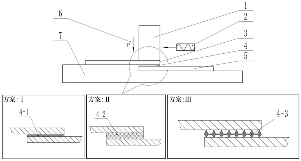
[0080] 1) Prepare the second fiber-reinforced thermoplastic composite material plate 3 and the first fiber-reinforced thermoplastic composite material plate 5 whose dimensions are 101.6 mm in length, 25.4 mm in width and 2 mm in thickness;

[0081] 2) adding carbon nanotubes or graphene into the ethanol solution for ultrasonic stirring, and making 5ml of a suspension with a concentration of 5mg / mL;

[0082] 3) Apply the suspension prepared in the above 2) evenly on the area to be welded of the first fiber reinforced thermoplastic composite material plate 5, and perform drying treatment at a temperature of 60° C. for 10 minutes to obtain carbon nanotubes or Graphene interfacial inclusion zone 4-1;

[0083] 4) Place the carbon nanotube or graphene interfacial inclusion region 4-1 obtained on the first fiber-reinforced thermoplastic composite material plate 5 treated above facing up and directly below the ultrasonic welding head 1, and fix it on the welding anvil 7 ;

[0084] (...

Embodiment 2

[0092] 1) Prepare the second fiber-reinforced thermoplastic composite material plate 3 and the first fiber-reinforced thermoplastic composite material plate 5 whose dimensions are 101.6 mm in length, 25.4 mm in width and 2 mm in thickness;

[0093] 2) adding carbon nanotubes or graphene into the ethanol solution for ultrasonic stirring, and making 5ml of a suspension with a concentration of 5mg / mL;

[0094] 3) Apply the suspension prepared in the above 2) evenly on the area to be welded of the first fiber reinforced thermoplastic composite material plate 5, and perform drying treatment at a temperature of 60° C. for 10 minutes to obtain carbon nanotubes or Graphene interfacial inclusion zone 4-1;

[0095] 4) Place the carbon nanotube or graphene interfacial inclusion region 4-1 obtained on the first fiber-reinforced thermoplastic composite material plate 5 treated above facing up and directly below the ultrasonic welding head 1, and fix it on the welding anvil 7 ;

[0096] (...

Embodiment 3

[0103] 1) Prepare the second fiber-reinforced thermoplastic composite material plate 3 and the first fiber-reinforced thermoplastic composite material plate 5 whose dimensions are 101.6 mm in length, 25.4 mm in width and 2 mm in thickness;

[0104] 2) adding carbon nanotubes or graphene into the ethanol solution for ultrasonic stirring, and making 5ml of a suspension with a concentration of 30mg / mL;

[0105] 3) Apply the suspension prepared in the above 2) evenly on the area to be welded of the first fiber reinforced thermoplastic composite material plate 5, and perform drying treatment at a temperature of 60° C. for 10 minutes to obtain carbon nanotubes or Graphene interfacial inclusion zone 4-1;

[0106] 4) Place the carbon nanotube or graphene interfacial inclusion region 4-1 obtained on the first fiber-reinforced thermoplastic composite material plate 5 treated above facing up and directly below the ultrasonic welding head 1, and fix it on the welding anvil 7 ;

[0107] ...


PUM


Abstract

The invention discloses an interface inclusion reinforced thermoplastic composite material ultrasonic welding method. Carbon nano tubes, graphene, SiC particles or high-strength metal net nails are adopted to prepare an interface inclusion area on an area to be welded of a first fiber reinforced thermoplastic composite material plate; the area to be welded of a second fiber reinforced thermoplastic composite plate is in lap joint with the interface inclusion area of the first fiber reinforced thermoplastic composite plate and fixed to an anvil block; and an ultrasonic welding head is used for applying welding pressure and sine displacement load perpendicular to the interface of the workpiece to the position over the area to be welded of the second fiber reinforced thermoplastic composite plate, and after welding is completed, the ultrasonic welding head is used for performing pressure maintaining on the welding joint, cooling is performed, then unloading is performed, and welding is completed. According to the invention, the tensile/peel strength of the welding joint is greatly improved.

Description

technical field [0001] The invention belongs to the technical field of ultrasonic connection of thermoplastic composite materials, and in particular relates to an ultrasonic welding method of thermoplastic composite materials reinforced by interfacial inclusions. Background technique [0002] The stiffness and shear strength of ultrasonic spot welded joints are almost equal to or higher than those of mechanically fastened joints, but due to the low tensile / peel strength of ultrasonically welded thermoplastic composite products, ultrasonic welding is rarely used in the engineering field. For joining carbon fiber reinforced thermoplastic structures. [0003] The interface strength of the welded joint directly determines the strength of the fiber-reinforced thermoplastic composite ultrasonically welded joint, and the fiber surface is too smooth, chemically inert and low in surface energy, and the anti-stripping strength between the fiber and the resin at the welding interface i...

Claims


Application Information

Patent Timeline
IPC IPC(8): B29C65/08
CPCB29C65/08B29C66/80
Inventor 张琦段文杰韩宾徐宏图
Owner XI AN JIAOTONG UNIV
Why Eureka
Try Eureka