
Fluid catalytic cracking oil and gas separation and steam stripping equipment and method

A technology of stripping and equipment, which is applied in fluid catalytic cracking oil-gas separation and stripping equipment and its fields, can solve the problems of long residence time, thermal cracking reaction, increasing the difficulty of stripping in the stripping section, etc., and achieve sufficient stripping Effect

Active Publication Date: 2013-11-06
CHINA PETROLEUM & CHEM CORP +1
View PDF7 Cites 0 Cited by
  • Summary
  • Abstract
  • Description
  • Claims
  • Application Information

AI Technical Summary

Problems solved by technology

However, the problem with this method is that the different types of hydrocarbons carried by the raw catalyst are not stripped separately, causing some easily stripped hydrocarbons to stay in the settler for too long, resulting in excessive cracking reactions and thermal cracking reactions
The reaction oil gas generated by this method contains a large amount of catalytic wax oil with a boiling point greater than 350°C, and even fractions with a boiling point greater than 500°C. Difficulty

Method used


Image

  • Fluid catalytic cracking oil and gas separation and steam stripping equipment and method

Examples


Embodiment Construction

[0032] The method provided by the present invention will be further described below in conjunction with the accompanying drawings, but the present invention is not thereby limited. The present invention is not limited to two-stage cyclone separation and two-stage stripping, and one or more stages can be added in a similar connection mode after two-stage cyclone separation and two-stage stripping. A coaxial type may also be a non-coaxial type.

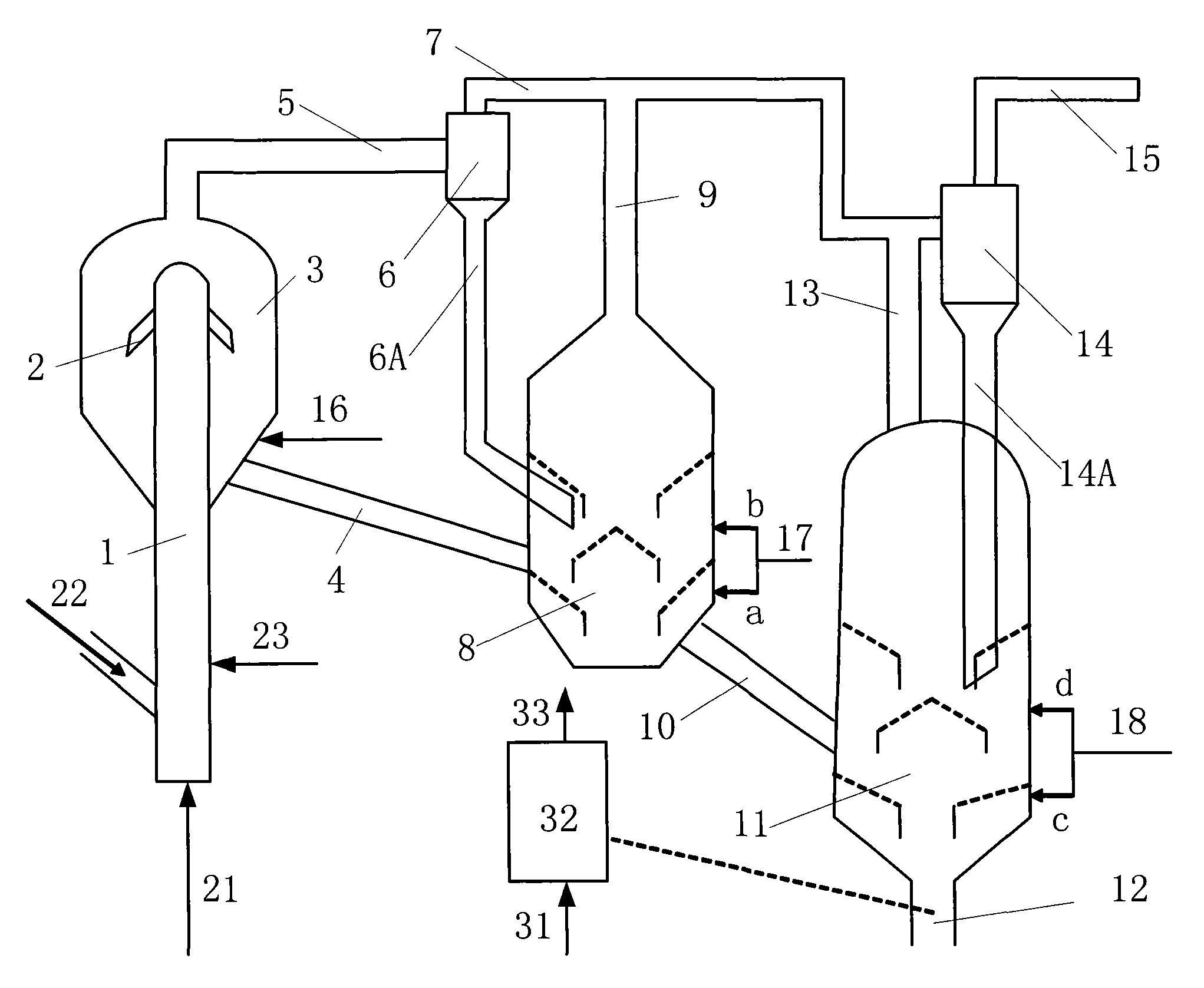
[0033] The accompanying drawing is a schematic flow chart of the apparatus and method of the present invention.

[0034] The fluidized catalytic cracking oil and gas separation and stripping equipment provided by the present invention includes an inertial separator 2, a pre-stripping device 3, a first-stage cyclone separator 6, a first stripper 8, a second-stage cyclone separator 14 and a second steam stripper Stripper 11, wherein each cyclone separator is provided with a plurality of cyclone separators, each cyclone separator is provi...


PUM


Abstract

The invention relates to fluid catalytic cracking oil and gas separation and steam stripping equipment. The equipment comprises an inertia separator, a pre-stripper, a first-stage cyclone separator, a second-stage cyclone separator, a first stripper and a second stripper, wherein the inertia separator is positioned in the pre-stripper; the gas phase outlet of the pre-stripper is connected with the inlet of the first-stage cyclone separator; diplegs of the first-stage and second-stage cyclone separators extend into the first and second strippers respectively; the gas phase outlets of the first-stage cyclone separator, the first stripper and the second stripper are connected with the inlet of the second-stage cyclone separator; and the first stripper is connected with the pre-stripper and the second stripper through catalyst pipelines respectively. A fluid catalytic cracking oil and gas separation and steam stripping method comprises the following steps of: separating reaction oil gas from a catalyst by using the inertia separator; stripping the catalyst by using the pre-stripper, the first stripper and the second stripper in turn and feeding the stripped catalyst into a regenerator; separating all reaction oil gas in the first-stage cyclone separator; and feeding an obtained gas phase and the gas phase obtained by every stripping into the second-stage cyclone separator for separating. In the equipment and the method, the reaction oil gas can be rapidly led out of a device and gas-phase hydrocarbons carried in particle gaps of the catalyst are stripped and led out rapidly, so that internal coking tendency of the device is reduced.

Description

technical field [0001] The invention relates to equipment and technology in catalytic cracking process. More specifically, the liquid catalytic cracking oil and gas separation and stripping equipment and method are used to increase the yield of liquid products, reduce the coke yield and reduce the tendency of coking inside the settler. Background technique [0002] The development of rapid separation technology in the riser outlet area has always been one of the important goals of riser reactor research, because the rapid separation device in the riser outlet area has two main functions. , quickly separated from the catalyst, avoiding the thermal cracking reaction, thereby increasing the yield of the target product; the second is to minimize the catalyst being carried out with the oil and gas, and reduce the particle concentration at the inlet of the cyclone separator, thereby reducing the unit consumption of the catalyst. At present, the rapid separation devices in the out...

Claims


Application Information

Patent Timeline
IPC IPC(8): C10G11/18B01D45/16B01J38/06
Inventor 许友好程从礼龚剑洪崔守业唐津莲刘守军
Owner CHINA PETROLEUM & CHEM CORP
Learn More