Resistor pin bending device with adjusting function
A technology of bending device and resistor, which is applied in the field of electronic product processing, can solve the problems of slow processing efficiency, poor control of bending position, and difficult control of resistance strength, etc., and achieve the effect of improving processing speed
- Summary
- Abstract
- Description
- Claims
- Application Information
AI Technical Summary
Problems solved by technology
Method used
Image
Examples
Embodiment 1
[0065] A resistor pin bending device with adjustment functions, such as figure 1 As shown, including: including the lower bottom plate 1, the vertical plate 101, the upper bottom plate 102, the bracket 103, the collecting bin 104, the stamping assembly and the lower mold assembly are located at the bottom, vertical plate 101 of all devices. The lower side is fixedly connected to the right rear side of the lower bottom plate 1, and the upper bottom plate 102 is fixed to the upper side of the vertical support 101, the bracket 103 is fixed to the upper bottom plate 102, and the collecting bin 104 is placed on the upper left side, stamping assembly of the lower bottom plate 1. Connect with the bracket 103, the lower mold assembly is connected to the lower bottom plate 1.
[0066] The staff first placed the resistor on the lower mold assembly, then start the stamping component, at which time the stamping assembly cooperates with the mold assembly to punching the resistance on both side...
Embodiment 2
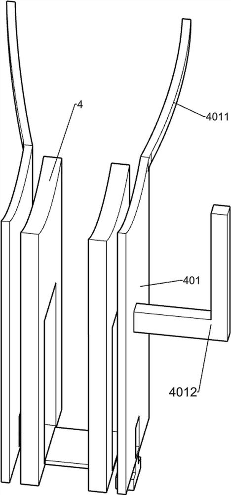
[0068] Specific reference Figures 2 to 4On the basis of Example 1, the stamping assembly includes a cylinder 2, a T block 201, a circular pin rod 202, a top bend 204, a spring 123, a cross plate 205, a stamped head 206, and a screw 207, and a cylinder 2 is mounted in On the bracket 103, the T block 201 is fixed to the telescoping rod of the cylinder 2, and two of the round pin 202 are respectively symmetrically disposed, and the round pin rod 202 is provided on the T block 201 and slides thereto, and the upper bending plate 204 and two The lower end of the round pin 202 is fixed, and there are two, spring 123, and each of the round pin 202 has a spring 123, and the upper and lower ends of the spring 123 are in contact with T block 201 and the upper curved plate 204, respectively. The board 205 is asymmetrically provided with two, and the inner end of the cross plate 205 is fixed to the T block 201, and two of the stamped head 206, two of the two punch heads 206 are slidably connec...
Embodiment 3
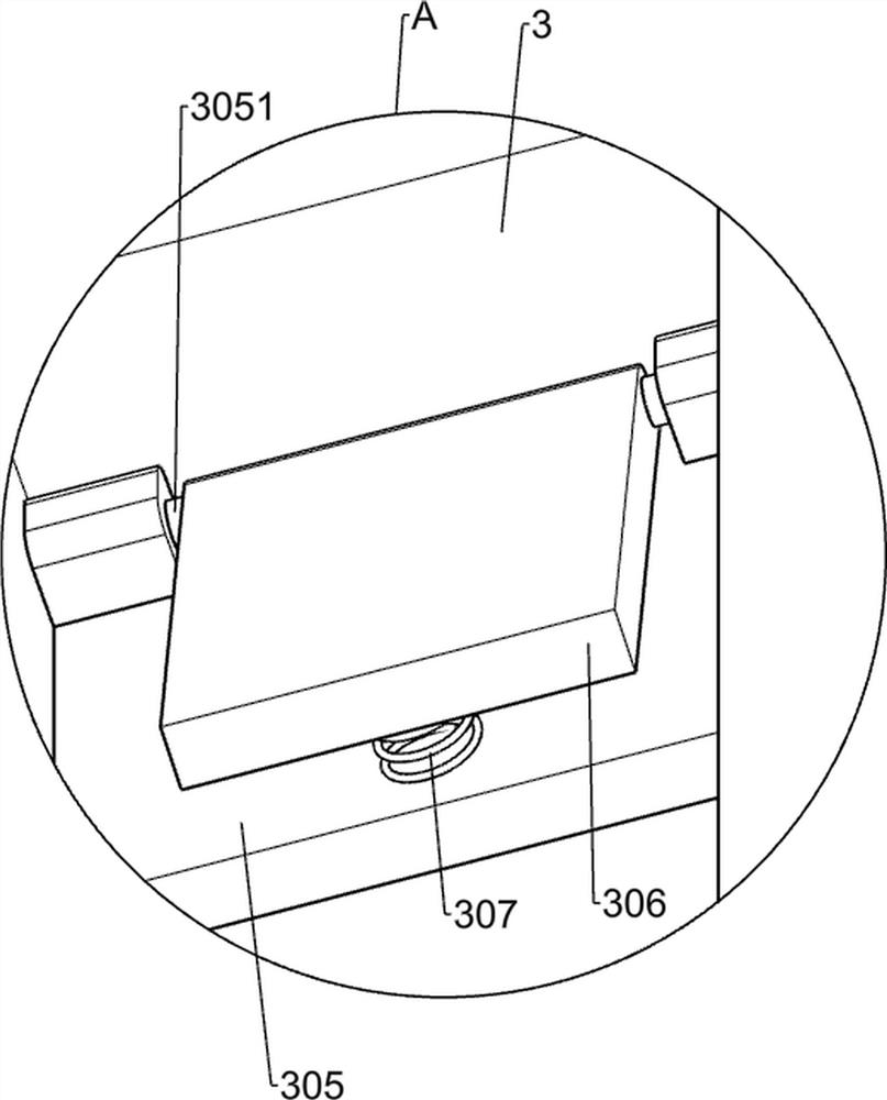
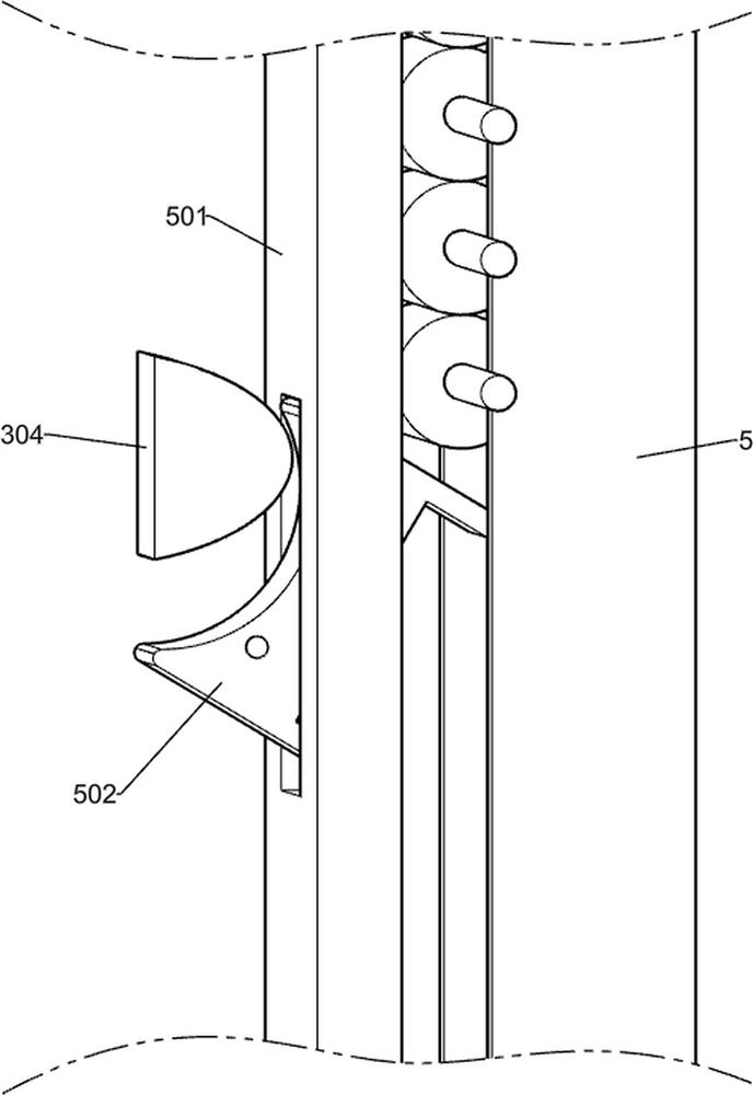
[0073] Specific reference Figure 5 to 8 As shown, on the basis of Example 2, there is also a connecting rod 3, a shaft one 301, a triangular block 302, a cross-baffle 303, a bump 304, a square plate 305, a shaft 2 3051, a reset plate 306, and a spring. 307. The upper end of the connecting rod 3 is fixed to the T block 201, and the rotating shaft one 301 is rotatable with the lower end of the connecting rod 3, and the triangular block 302 is fixed to the rotating shaft one 301, and the triangular block 302 is in contact with the connecting rod 3, and the cross stop 303 The rear side is fixed to the lower end of the connecting rod 3, and the cross-baffle 303 is in contact with the triangular block 302, the bump 304 is fixed to the upper right side of the connecting rod 3, and the square plate 305 is close to the bump 304, and the square plate 305 is fixed to the connecting rod 3. The rotation axis 251 is rotated on the upper side of the square plate 305, and the reset plate 306 is f...
PUM
 Abstract
Description
Claims
Application Information
 - R&D
- Intellectual Property
- Life Sciences
- Materials
- Tech Scout
- Unparalleled Data Quality
- Higher Quality Content
- 60% Fewer Hallucinations
Browse by: Latest US Patents, China's latest patents, Technical Efficacy Thesaurus, Application Domain, Technology Topic, Popular Technical Reports.
© 2025 PatSnap. All rights reserved.Legal|Privacy policy|Modern Slavery Act Transparency Statement|Sitemap|About US| Contact US: help@patsnap.com


