
Swing mechanism and shaving tool

A swing mechanism and drive mechanism technology, applied in metal processing, etc., can solve the problems of shortening the service life of the shaving tool, increasing the noise of the razor, affecting the shaving performance, etc., and improving the shaving performance And the use of safety, improve the use of comfort, reduce the effect of vibration

Pending Publication Date: 2021-06-25
浙江海顺电工有限公司
View PDF1 Cites 0 Cited by
  • Summary
  • Abstract
  • Description
  • Claims
  • Application Information

AI Technical Summary

Problems solved by technology

Secondly, this document also discloses that both sides of the first swing frame (13) and the second swing frame (14) are respectively provided with connecting parts (161) and spring parts (162) so that the first swing frame (13) and the second swing frame The frame (14) is W-shaped as a whole, although the first swing frame (13) and the second swing frame (14) can be fixedly connected to the body by using the connecting portion (161) and the elastic piece portion (162); Can only provide weak elastic force to keep the connection and reset of the first pendulum (13) and the second pendulum (14) with the body, when the eccentric shaft drives the first pendulum (13) to swing, the eccentric shaft and the first pendulum At the moment when the pendulum (13) contacts, the centrifugal force generated by the rotation of the eccentric shaft will suddenly force one side of the first pendulum (13). The swing frame (13) twists or moves up and down (twist refers to the rotation of the first swing frame (13) along the rotation direction of the eccentric shaft), which causes the blade to touch the static blade mesh or the side wall, affecting the shaving performance While increasing the noise of the razor, the edge of the blade wears faster and the temperature rise of the blade is increased, which shortens the service life of the blade and the trimming comfort of the shaving tool

Method used


Image

  • Swing mechanism and shaving tool
  • Swing mechanism and shaving tool
  • Swing mechanism and shaving tool

Examples


Embodiment Construction

[0022] Embodiments of the present invention will be further described below in conjunction with accompanying drawings:

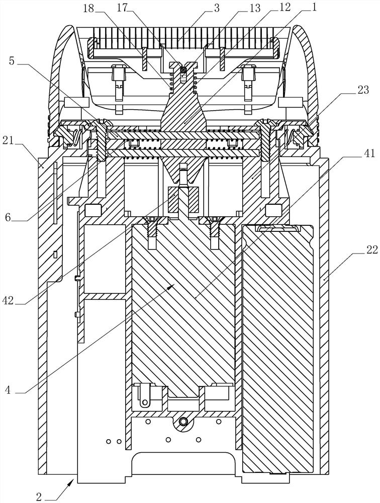
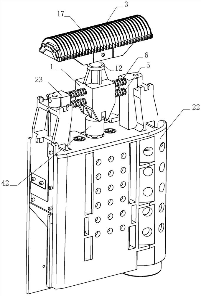
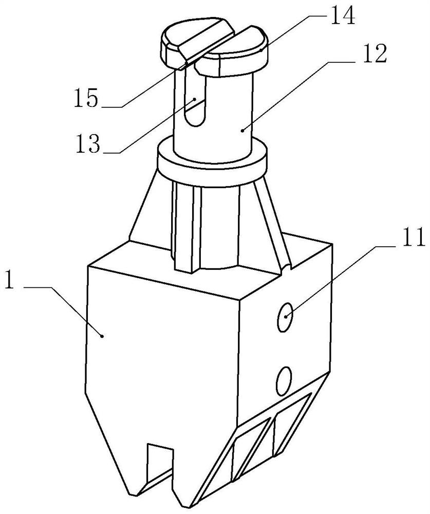
[0023] like Figure 1-4 As shown, the present invention is a swing mechanism, including a swing seat 1, the swing seat 1 is installed in the housing 2 and its upper end is connected with the movable knife 3, and its lower end is linked with the driving mechanism 4 installed in the housing 2 ; The housing 2 is provided with a limit mechanism 5, and the swing base 1 can move horizontally along the limit mechanism 5 under the drive of the drive mechanism 4 and is dynamically connected with the limit mechanism 5. By adding a limit mechanism 5 in the housing 2 and dynamically connecting the swing seat 1 to the limit mechanism 5, when the drive mechanism 4 starts, it can drive the swing seat 1 to move horizontally along the limit mechanism 5, avoiding the When the driving mechanism 4 is started, the swing seat 1 twists or moves, preventing the blade of the moving...


PUM


Abstract

The invention relates to a swing mechanism and a shaving tool. The swing mechanism is characterized in that a limiting mechanism is arranged in a shell, and a swing seat can horizontally reciprocate along the limiting mechanism under the driving of a driving mechanism and is movably connected with the limiting mechanism. The swing mechanism has the beneficial effects that the limiting mechanism is additionally arranged in the shell, and the swing seat is movably connected with the limiting mechanism, so that when the driving mechanism is started, the swing seat can be driven to horizontally reciprocate along the limiting mechanism, and the swing seat is prevented from twisting or moving at the moment when the driving mechanism is started; and a cutting edge of a moving cutter is prevented from extruding a static mesh and the side wall of a static cutter, noise of the shaving tool is reduced, cutting edge abrasion of a blade is relieved, the service life of the moving cutter is prolonged, and the overall comfort of the shaving tool is improved.

Description

technical field [0001] The present invention relates to an oscillating mechanism, more particularly to an oscillating mechanism used on a hair trimming tool. Background technique [0002] The applicant applied for a patent for invention on May 10, 2012: a shaver and its cutter head device, notification number: CN 102642213 B, a swing mechanism is recorded in this patent document, and the swing mechanism is composed of The first pendulum frame (13) and the second pendulum frame (14) are composed of an eccentric shaft to drive the first pendulum frame (13) and the second pendulum frame (14) to reciprocate and horizontally swing, thereby realizing the movement of the moving knife along the static knife mesh. Swing back and forth horizontally to trim hair. Secondly, this document also discloses that both sides of the first swing frame (13) and the second swing frame (14) are respectively provided with connecting parts (161) and spring parts (162) so that the first swing frame (...

Claims


Application Information

Patent Timeline
IPC IPC(8): B26B19/04B26B19/38
CPCB26B19/04B26B19/38
Inventor 不公告发明人
Owner 浙江海顺电工有限公司
Learn More