Finished product collecting device for additive printer and printer thereof

A finished product collection and printer technology, applied in additive processing, additive manufacturing, 3D object support structure, etc., can solve the problem of low storage efficiency of finished products, and achieve the effect of avoiding pollution, improving collection efficiency, and improving collection and storage effect.

Pending Publication Date: 2021-06-25
HEFEI AIRWREN AUTOMATIC EQUIP CO LTD
View PDF1 Cites 0 Cited by
  • Summary
  • Abstract
  • Description
  • Claims
  • Application Information

AI Technical Summary

Problems solved by technology

The above-mentioned device makes the corresponding printer body push the corresponding printed finished product directly after completing the corresponding printing process through the corresponding receiving box, the motor, the gear, the rack, the placement slot, the placement table, and the cylinder on the inner side of the base. To the corresponding receiving box for corresponding storage, but the storage efficiency of finished products is low

Method used


Image

  • Finished product collecting device for additive printer and printer thereof
  • Finished product collecting device for additive printer and printer thereof
  • Finished product collecting device for additive printer and printer thereof

Examples


Embodiment 1

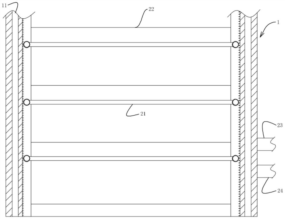
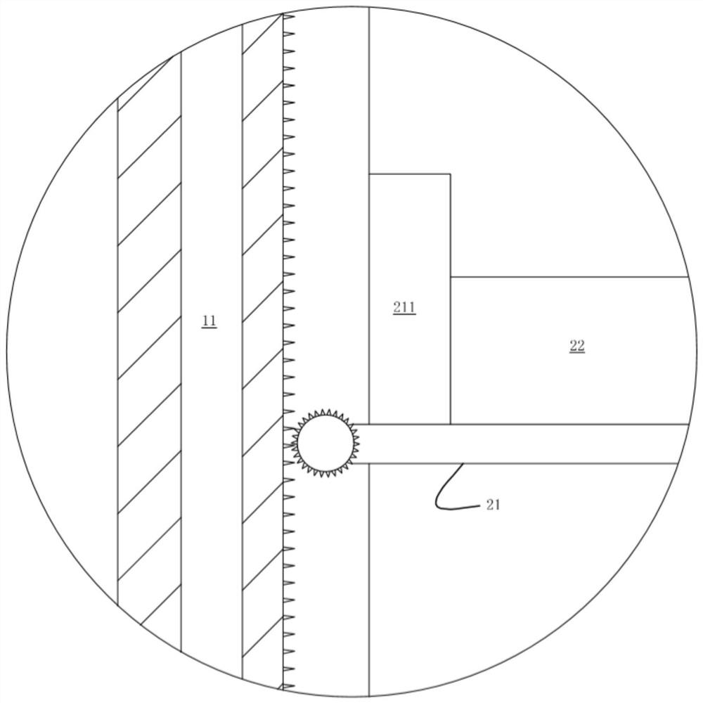
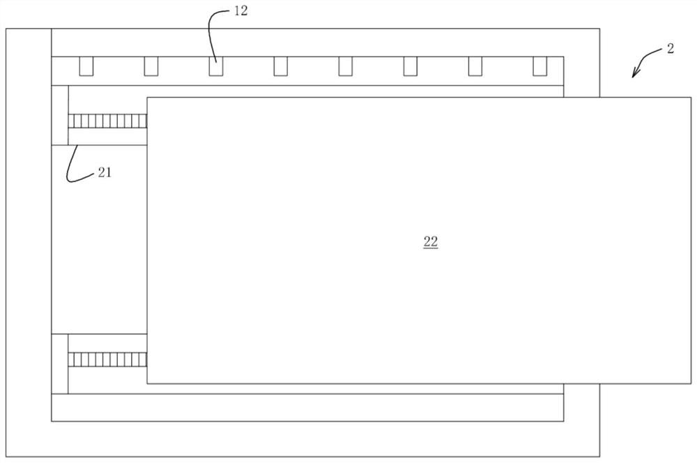
[0022] A finished product collection device for an additive printer, comprising a collection box body 1 and a finished product placement device movably arranged in the collection box body 1, the finished product placement device 2 includes a number of finished product carriers vertically slidably arranged in the collection box body 1 The frame 21 and the auxiliary printing flat plate 22 horizontally slidably arranged on the finished product carrier 21 are provided with an opening for the auxiliary printing flat plate 22 to pass through near the right end of the collection box body 1. After the printing is completed, the printing flat plate located in the additive printer The auxiliary printing plate 22 on the top slides onto the finished product carrier 21 and conflicts with the limit plate 211 located at the left end of the finished product carrier 21. The collection box body 1 is provided with a gas circulation channel 11 for gas circulation, located in the collection box body...

Embodiment 2

[0025] An additive printer, including the finished product collection device for the additive printer described in Embodiment 1, and also includes an auxiliary collection box body 3 for switching and printing the auxiliary printing plate 22, and there are several auxiliary collection box bodies 3 The auxiliary carrier frame III31 for placing the auxiliary printing plate 22, and the auxiliary carrier frame III31 is vertically slid in the auxiliary collection box body 3, wherein the other end of the auxiliary carrier frame II24 is in sliding contact with the auxiliary collection box body 3 , the auxiliary printing plate 22 slides to the auxiliary carrier III 31 through the auxiliary carrier II 24 , and through the conveying action of the auxiliary carrier III, the auxiliary printing plate 22 slides to the printing plate of the additive printer, and the printing is collected and printed in sequence.

[0026] The principle of use of the present invention: specifically, in the initi...


PUM


Abstract

The invention provides a finished product collecting device for an additive printer and the printer thereof. The device comprises a collecting box body and a finished product placing device movably arranged in the collecting box body. The finished product placing device comprises a plurality of finished product bearing frames vertically arranged in the collecting box body in a sliding mode and auxiliary printing flat plates horizontally arranged on the finished product bearing frames in a sliding mode, and an opening used for allowing the auxiliary printing flat plates to penetrate through is formed in the position close to the right end of the collecting box body. After printing is completed, the auxiliary printing flat plates located on a printing flat plate in the additive printer slide onto the finished product bearing frames and abut against limiting plates located at the left ends of the finished product bearing frames. Through cooperation of the auxiliary printing flat plates, the auxiliary bearing frames I and the finished product bearing frames, finished products can be efficiently and preliminarily collected and treated, the finished products can be continuously discharged and conveyed by being matched with the auxiliary bearing frames II, and therefore the collecting efficiency of the finished products in the printing process is improved.

Description

technical field [0001] The invention relates to the technical field of printer equipment, in particular to a finished product collection device for an additive printer and a printer thereof. Background technique [0002] Publication number CN109049711B provides an additive printer with a material receiving mechanism, including a printer body, a printer inner cavity is left inside the printer body, a fixing frame is left inside the printer inner cavity, and the fixed A base is left at the bottom of the frame, a receiving box is left at the left end of the base, and protrusions are left at the upper ends of the left and right sides of the base. The above-mentioned device makes the corresponding printer body push the corresponding printed finished product directly after completing the corresponding printing process through the corresponding receiving box, the motor, the gear, the rack, the placement slot, the placement table, and the cylinder on the inner side of the base. To ...

Claims


Application Information

Patent Timeline
Patent Type & Authority Applications(China)
IPC IPC(8): B29C64/35B29C64/379B29C64/20B33Y30/00B33Y40/00
CPCB33Y30/00B33Y40/00B29C64/20B29C64/35B29C64/379
Inventor 龙梅
Owner HEFEI AIRWREN AUTOMATIC EQUIP CO LTD
Why Eureka
Try Eureka