A laser scanning tunnel intelligent monitoring system and method

A laser scanning and monitoring system technology, which is applied in the directions of measuring devices, cross-section drawing, surveying and navigation, etc., can solve problems such as large limitations, affecting detection accuracy, and deviation from straight-line moving direction, and achieve the effect of preventing damage

Active Publication Date: 2022-05-20
HUNAN ZHILI ENG SCI & TECH
View PDF5 Cites 0 Cited by
  • Summary
  • Abstract
  • Description
  • Claims
  • Application Information

AI Technical Summary

Problems solved by technology

It is very important in tunnel excavation construction. It controls the plane, shape and section geometry of tunnel excavation, which is related to the penetration of tunnel. The scanning instrument is used for monitoring. Due to the need for multi-point monitoring, multiple scanning instruments need to be arranged, and the alignment and positioning of the instruments is quite inconvenient. The tunnel laser 3D scanner improved by the existing technology has a car body part at the chassis, but the limitations Larger, only after the track is laid out in the later stage can the detection be moved along the track. If it is used for over- and under-break analysis, it will cause large bumps when moving on the uneven soil surface, which will affect the detection accuracy and deviate from the straight line at the same time. direction of movement

Method used


Image

  • A laser scanning tunnel intelligent monitoring system and method
  • A laser scanning tunnel intelligent monitoring system and method
  • A laser scanning tunnel intelligent monitoring system and method

Examples


Embodiment Construction

[0037] The following description serves to disclose the present invention to enable those skilled in the art to carry out the present invention. The preferred embodiments described below are only examples, and those skilled in the art can devise other obvious variations.

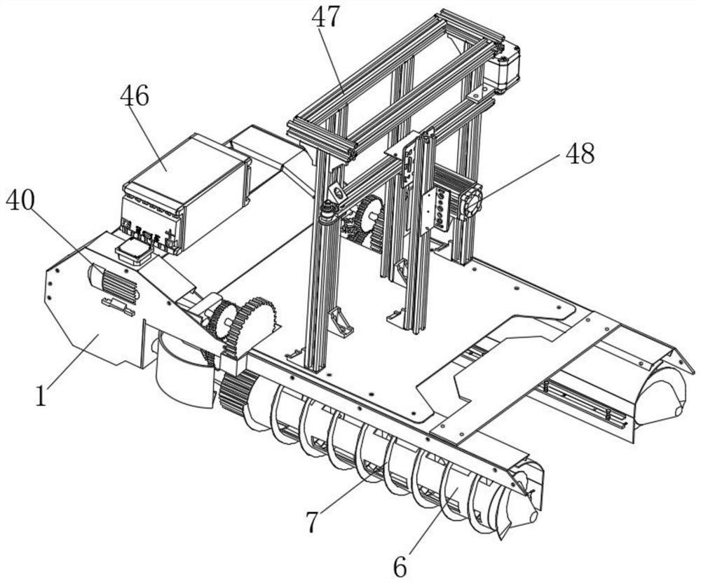
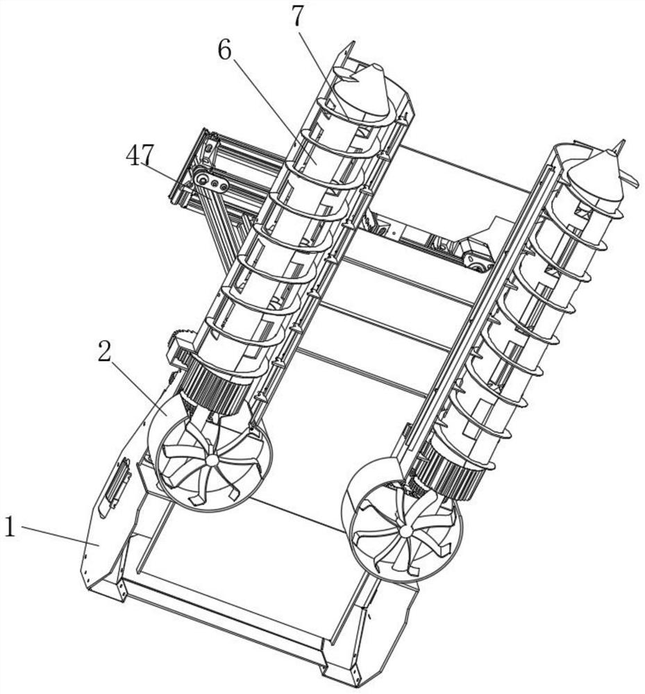
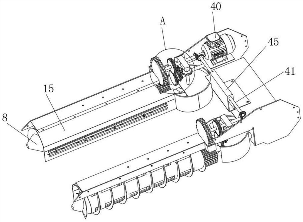
[0038] Such as Figure 1-Figure 13 The shown intelligent monitoring system for a laser scanning tunnel includes an underframe 1, and the lower end surface of the underframe 1 is respectively provided with a symmetrical screw-in mechanism near the edges on both sides. The fixed shell 2 on the end face, the fixed shaft 3 that is fixedly connected to the inner wall of the fixed shell 2 and extends forward, the conical head 8 that is rotatably connected to the front end of the fixed shaft 3, and the rotary shaft that extends backward from the edge of the rear end of the conical head 8. The inlet cylinder 6 is fixedly connected to the outer surface of the screw-in cylinder 6 and the screw-in blade 7 that is push...


PUM


Abstract

The present invention relates to the technical field of tunnel monitoring, in particular to an intelligent monitoring system for laser scanning tunnels, which includes an underframe, and the lower end surface of the underframe near the edges on both sides is respectively provided with symmetrical screw-in mechanisms, and the screw-in mechanism The mechanism includes a fixed shell fixedly installed on the lower end surface of the chassis, a fixed shaft fixedly connected to the inner wall of the fixed shell and extending forward, a conical head rotatably connected to the front end of the fixed shaft, and extending backward from the edge of the rear end of the conical head. The precession cylinder, the precession blade that is fixedly connected to the outer surface of the precession cylinder and is pushed forward when it rotates, the present invention also provides a method for using the laser scanning tunnel intelligent monitoring system, the entire monitoring system of the present invention The system will advance steadily in the process of advancing, which is beneficial to the monitoring of the tunnel section in the analysis of over and under excavation, and solves the inconvenience caused by the traditional multi-point arrangement of the main body of the infrared monitoring instrument, and also solves the monitoring caused by the unstable movement The problem of poor precision.

Description

technical field [0001] The invention relates to the technical field of tunnel monitoring, in particular to a laser scanning tunnel intelligent monitoring system and method. Background technique [0002] Tunnel section measurement is a measurement work that must be carried out during tunnel construction and completion acceptance. It is very important in tunnel excavation construction. It controls the plane, construction and section geometry of tunnel excavation, which is related to the penetration of tunnel. The scanning instrument is used for monitoring. Due to the need for multi-point monitoring, multiple scanning instruments need to be arranged, and the alignment and positioning of the instruments is quite inconvenient. The tunnel laser 3D scanner improved by the existing technology has a car body part at the chassis, but the limitation Larger, only after the track is laid out in the later stage can the detection be moved along the track. If it is used in the analysis pro...

Claims


Application Information

Patent Timeline
Patent Type & Authority Patents(China)
IPC IPC(8): G01C7/06
CPCG01C7/06Y02B10/30
Inventor 鲁光银朱建军汤井田邹俊华曾明许准张家松肖晓
Owner HUNAN ZHILI ENG SCI & TECH
Why Eureka
Try Eureka