
AOC optical module and electrified aging method thereof

A technology of optical module and optical transceiver module, which is applied in the field of optical communication, can solve problems such as component drop, fiber breakage, and limited space, and achieve the effects of ensuring performance reliability, avoiding fiber breakage, and convenient disassembly

Active Publication Date: 2021-06-25
WUHAN HUAGONG GENUINE OPTICS TECH
View PDF4 Cites 0 Cited by
  • Summary
  • Abstract
  • Description
  • Claims
  • Application Information

AI Technical Summary

Problems solved by technology

[0002] In the process of making AOC optical modules, the optical modules need to be aging with electricity, but because the AOC optical modules are two modules that transmit each other, they need to be put into the aging box to work at the same time; AOC optical cables are as short as 1m and as long as tens of meters. After being assembled into a module, it cannot be separated from the module, so only one pair of AOC optical module + optical cable can be put into the aging box at the same time for aging
The aging box has limited space, and only a limited number of AOC optical modules can be placed in one job, which seriously affects the live aging efficiency of AOC optical modules and affects the production efficiency of optical modules
[0003] The upper cover of the existing AOC optical module is integrated and can only be disassembled as a whole. If the shell is removed to replace the self-loop optical fiber for live aging, it is easy to cause the optical fiber inside the module to break, the device is damaged, and the risk of components falling. Replaced with AOC optical cable, the performance and reliability of the module cannot be guaranteed after the shell is installed again

Method used


Image

  • AOC optical module and electrified aging method thereof
  • AOC optical module and electrified aging method thereof
  • AOC optical module and electrified aging method thereof

Examples


Embodiment Construction

[0028] The following will clearly and completely describe the technical solutions in the embodiments of the present invention with reference to the accompanying drawings in the embodiments of the present invention. Obviously, the described embodiments are only some, not all, embodiments of the present invention. Based on the embodiments of the present invention, all other embodiments obtained by persons of ordinary skill in the art without making creative efforts belong to the protection scope of the present invention.

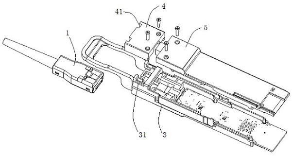
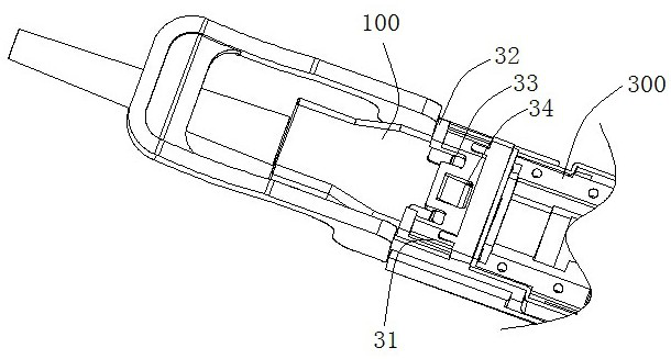
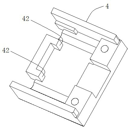
[0029] Such as figure 1 and figure 2 As shown, the embodiment of the present invention provides an AOC optical module, including an AOC optical cable assembly 100 and an AOC optical transceiver module 300 that are plugged and fixed to each other. The AOC optical cable assembly 100 includes a housing 1 and an optical cable assembly located in the housing 1 2. The AOC optical transceiver module 300 includes a base assembly 3, an upper cover assembly and an opt...


PUM


Abstract

The invention provides an AOC optical module and an electrified aging method thereof. The AOC optical module comprises an AOC optical cable assembly and an AOC optical transceiver module which are mutually inserted and fixed, the AOC optical cable assembly comprises a shell and an optical cable assembly located in the shell, and the AOC optical transceiver module comprises a base assembly, an upper cover assembly and an optical transceiver assembly. The optical transceiver assembly is located in the base assembly, the upper cover assembly comprises a first upper cover and a second upper cover, the first upper cover and the second upper cover jointly cover and seal the base assembly, and the front end of the base assembly is provided with a butt joint cavity allowing a shell of the AOC optical cable assembly to be connected in an inserted mode. The first upper cover is arranged above the butt joint cavity in a covering mode and is locked and fixed to the shell. The AOC optical module is high in electrified aging efficiency and high in quality, the main body part of the optical module does not need to be disassembled, the risks of optical fiber breakage, device damage and component falling in the optical module are avoided, and the performance reliability of the module after re-casing is guaranteed.

Description

technical field [0001] The invention belongs to the technical field of optical communication, and in particular relates to an AOC optical module and a charged aging method thereof. Background technique [0002] In the process of making AOC optical modules, the optical modules need to be aging with electricity, but because the AOC optical modules are two modules that transmit each other, they need to be put into the aging box to work at the same time; AOC optical cables are as short as 1m and as long as tens of meters. After being assembled into a module, it cannot be separated from the module, so only one pair of AOC optical module + optical cable can be put into the aging box at the same time for aging. The aging box has limited space, and only a limited number of AOC optical modules can be placed in one job, which seriously affects the live aging efficiency of AOC optical modules and affects the production efficiency of optical modules. [0003] The upper cover of the exi...

Claims


Application Information

Patent Timeline
Patent Type & Authority Applications(China)
IPC IPC(8): G02B6/38
CPCG02B6/3869G02B6/3825
Inventor 杨亚强胡长飞李梓文许其建汤彪刘树林舒坤
Owner WUHAN HUAGONG GENUINE OPTICS TECH
Learn More