Tree section peeling device

A technology for trees and wood segments, applied in the field of tree segment peeling devices, can solve problems such as reduced work efficiency, increased pits on the surface of wood segments, and inability to adjust rotors, and achieves the effects of reducing peeling force and improving work efficiency.

Active Publication Date: 2021-06-29
泉州市池瑞科技有限公司
View PDF10 Cites 1 Cited by
  • Summary
  • Abstract
  • Description
  • Claims
  • Application Information

AI Technical Summary

Problems solved by technology

[0003] 1. When there are too many wood sections, the upper wood section is not easy to roll to the lower layer for peeling, resulting in uneven peeling effect, causing the peeled wood section to still contact the rotor during tumbling, which greatly increases the number of pits on the surface of the wood section. prone to surface damage
[0004] 2. The rotor cannot be adjusted. When the bark is thicker, the peeling efficiency is low. When the bark is thinner, it is easy to cause pits on the surface of the wood section.
[0005] 3. In the process of rolling a large number of wooden sections, they roll irregularly and often need to be corrected manually, which reduces work efficiency and increases the chance of accidental injury

Method used


Image

  • Tree section peeling device
  • Tree section peeling device
  • Tree section peeling device

Examples


specific Embodiment approach 1

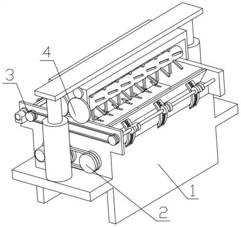
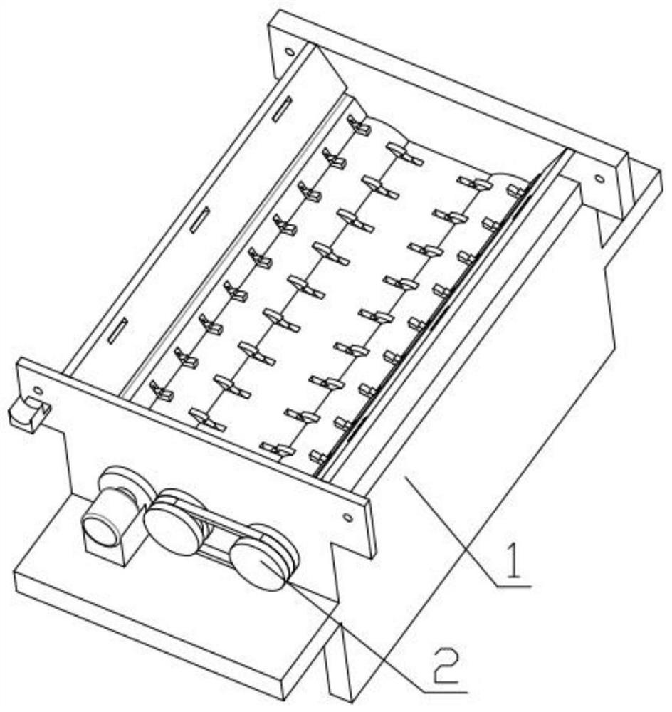
[0036] Combine below Figure 1-12 Description of this embodiment, a tree section peeling device, including a device box 1, a peeling mechanism 2, a wood section alignment mechanism 3 and an auxiliary rolling mechanism 4, the described stripping mechanism 2 is fixedly installed on the device box 1, and the wood section The alignment mechanism 3 is fixedly installed on the device box body 1 , and the auxiliary rolling mechanism 4 is fixedly installed on the device box body 1 .

specific Embodiment approach 2

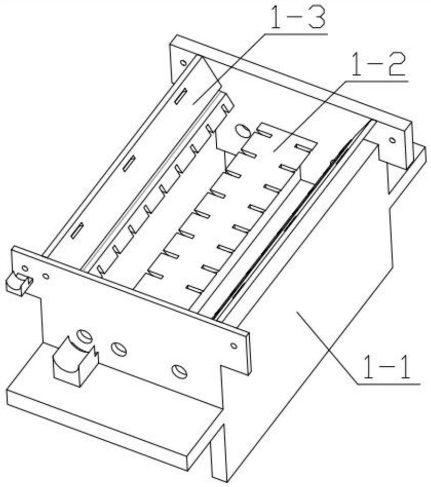
[0038] Combine below Figure 1-12 Describe this embodiment, this embodiment will further explain the first embodiment, the device box 1 includes a box body 1-1, a middle T-shaped plate 1-2, side baffles 1-3, the box body 1- 1 is fixedly installed with a middle T-shaped plate 1-2, and a side baffle 1-3 is fixedly installed on the box body 1-1;

[0039] The middle T-shaped plate 1-2 includes a T-shaped groove plate 1-2-1, a fixed horizontal plate 1-2-2, a limit column 1-2-3, an adjusting threaded rod 1-2-4, and a fixed horizontal plate 1 -2-2 is fixedly installed on the box body 1-1, and the limit post 1-2-3 is fixedly installed on the similar T-shaped slot plate 1-2-1, and the limit post 1-2-3 is slidably installed on the fixed horizontal In the through hole set on the plate 1-2-2, the adjusting threaded rod 1-2-4 is rotatably installed in the groove set on the T-shaped groove plate 1-2-1, and the adjusting threaded rod 1-2-4 is connected with the Fixed horizontal plate 1-2-2 t...

specific Embodiment approach 3

[0041] Combine below Figure 1-12 Illustrate this embodiment, this embodiment will further illustrate Embodiment 2, described peeling mechanism 2 comprises main motor 2-1, motor gear 2-2, first sprocket wheel 2-3, chain one 2-4, the first Two sprockets 2-5, one peeling shaft 2-6, two peeling shafts 2-7, the main motor 2-1 is fixedly installed on the box main body 1-1, and the output end of the main motor 2-1 is fixedly installed with motor gears 2-2, the motor gear 2-2 is fixedly connected with the peeling shaft one 2-6, the peeling shaft one 2-6 is rotatably installed in the groove provided on the box body 1-1, and the peeling shaft two 2-7 is rotatably installed in the In the groove provided on the casing main body 1-1, the peeling shaft two 2-7 is fixedly connected with the second sprocket wheel 2-5, and the second sprocket wheel 2-5 is meshed with the chain one 2-4, and the chain one 2- 4 Mesh with the first sprocket 2-3, the first sprocket 2-3 meshes with the motor gear ...


PUM


Abstract

The invention relates to a wood processing device, in particular to a tree section peeling device. The tree section peeling device comprises a device box body, a peeling mechanism, a wood section aligning mechanism and an auxiliary rolling mechanism, the peeling mechanism is fixedly installed on the device box body, the wood section aligning mechanism is fixedly installed on the device box body, and the auxiliary rolling mechanism is fixedly installed on the device box body. According to the tree section peeling device, in the peeling process, the placing positions of wood sections can be corrected, the peeling efficiency is improved, the peeling degree can be adjusted, adjustment can be conducted according to different tree types, when the number of the wood sections is too large, the wood sections can be assisted in rolling, and the working efficiency is improved.

Description

technical field [0001] The present invention relates to a wood processing device, more particularly to a tree segment peeling device. Background technique [0002] The high-efficiency double-rotor wood peeling machine is a new generation of high-efficiency wood peeling products innovatively developed on the basis of single rollers. Compared with single-roller peeling machines, the machine has higher working efficiency and cleaner peeling. The wood is less damaged and the design is more reasonable. But the inventor finds that it has the following problems during actual use: [0003] 1. When there are too many wood sections, the upper wood section is not easy to roll to the lower layer for peeling, resulting in uneven peeling effect, causing the peeled wood section to still contact the rotor during tumbling, which greatly increases the number of pits on the surface of the wood section. prone to surface damage [0004] 2. The rotor cannot be adjusted. When the bark is thicke...

Claims


Application Information

Patent Timeline
IPC IPC(8): B27L1/04B27L1/05
CPCB27L1/04B27L1/05
Inventor 胡兰波
Owner 泉州市池瑞科技有限公司
Why Eureka
Try Eureka