
Liftable undercarriage

A landing gear and elevating technology, applied in the field of elevating landing gear, can solve the problems of drone damage, inability to adjust the height of the hanging equipment, damage to the hanging equipment, etc., so as to avoid the effect of falling.

Pending Publication Date: 2021-06-29
南京云将新材料应用科技研究院有限公司
View PDF1 Cites 2 Cited by
  • Summary
  • Abstract
  • Description
  • Claims
  • Application Information

AI Technical Summary

Problems solved by technology

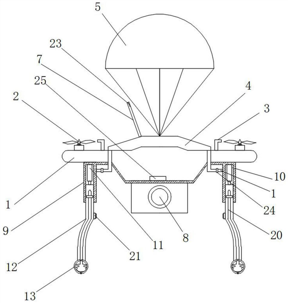
[0004] In the process of realizing the present invention, the inventors have found that at least the following problems in the prior art have not been resolved: when the prior art is in use, when the UAV malfunctions and stops running in the air, if it falls directly and touches the ground , it will lead to damage to the UAV, and the current UAV usually hangs equipment such as a camera, and the existing UAV landing gear cannot be adjusted according to the height of the hanging equipment when it is in use, which may lead to serious problems. The high hanging equipment is in contact with the raised objects on the ground, causing damage to the hanging equipment

Method used


Image

  • Liftable undercarriage
  • Liftable undercarriage
  • Liftable undercarriage

Examples


Embodiment Construction

[0025] In order to make the technical means, creative features, goals and effects achieved by the present invention easy to understand, the present invention will be further described below in conjunction with specific embodiments.

[0026] In describing the present invention, it should be understood that the terms "upper", "lower", "front", "rear", "left", "right", "top", "bottom", "inner", " The orientation or positional relationship indicated by "outside", etc. is based on the orientation or positional relationship shown in the drawings, and is only for the convenience of describing the present invention and simplifying the description, rather than indicating or implying that the referred device or element must have a specific orientation, so as to Specific orientation configurations and operations, therefore, are not to be construed as limitations on the invention.

[0027] In the description of the present invention, it should be noted that, unless otherwise specified and...


PUM


Abstract

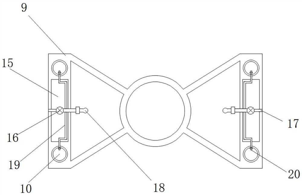
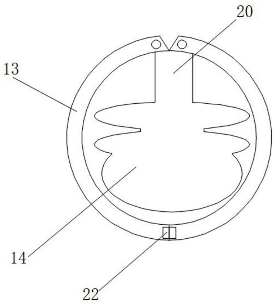
The invention relates to the technical field of undercarriages, and discloses a liftable undercarriage which comprises an unmanned aerial vehicle body, a single chip microcomputer is arranged in the unmanned aerial vehicle body, driving mechanisms are arranged at the four corners of the top side of the unmanned aerial vehicle body, and a rotating speed sensor is arranged on one side of each driving mechanism. And the bottom side of the rotating speed sensor is fixedly installed on the top side of the unmanned aerial vehicle body, a storage bin is fixedly installed on the top side of the unmanned aerial vehicle body, and a parachute is arranged in the storage bin. Through arrangement of the rotating speed sensor, an electromagnetic valve, a sucking pump, an air bag and the parachute, during use, when the unmanned aerial vehicle body stops running due to a fault in the flight process, the rotating speed sensor detects that the driving mechanism stops rotating, so that the single chip microcomputer controls the sucking pump and the electromagnetic valve to inflate air into the air bag and the storage bin; and the parachute is opened while the airbag expands, so that the unmanned aerial vehicle body stably falls, and the unmanned aerial vehicle body is prevented from being broken.

Description

technical field [0001] The invention relates to the technical field of landing gear, in particular to a liftable landing gear. Background technique [0002] With the development of science and technology, multi-rotor drones have gradually appeared in people's daily life. In recent years, drones have been constantly updated, and their structures and functions have been continuously enriched and optimized. [0003] The existing patent (publication number: CN212921957U) is an unmanned aerial vehicle landing gear device, which relates to the technical field of unmanned aerial vehicles. A landing gear device for an unmanned aerial vehicle, including a body, the body includes two landing units, and the two landing units are respectively located on both sides of the body; the landing unit includes a bottom rod and a cylinder connected to each other; Connection; the cylinders of the two lifting and landing units realize gas communication through pipes. The landing gear device of t...

Claims


Application Information

Patent Timeline
Patent Type & Authority Applications(China)
IPC IPC(8): B64C25/56B64D17/80B64D47/08
CPCB64C25/56B64D17/80B64D47/08B64U30/20B64U70/00B64U70/83B64U10/10
Inventor 许旭
Owner 南京云将新材料应用科技研究院有限公司
Learn More