Bidirectional locking mechanism of axle and highway-railway transport vehicle

A technology for locking mechanisms and transport vehicles, applied in the directions of axles, transportation and packaging, wheels, etc., can solve problems such as the unstable state of highway axles, and achieve the effect of improving the convenience of operation and driving safety

Active Publication Date: 2022-03-25
CRRC YANGTZE GRP CO LTD
View PDF8 Cites 2 Cited by
  • Summary
  • Abstract
  • Description
  • Claims
  • Application Information

AI Technical Summary

Problems solved by technology

[0005] Aiming at the defects existing in the prior art, the present application provides an axle-locking protection mechanism and a road-rail transport vehicle to solve the problem in the prior art that the state of the road axle of the road-rail vehicle is unstable under different working conditions

Method used


Image

  • Bidirectional locking mechanism of axle and highway-railway transport vehicle
  • Bidirectional locking mechanism of axle and highway-railway transport vehicle
  • Bidirectional locking mechanism of axle and highway-railway transport vehicle

Examples


Embodiment 1

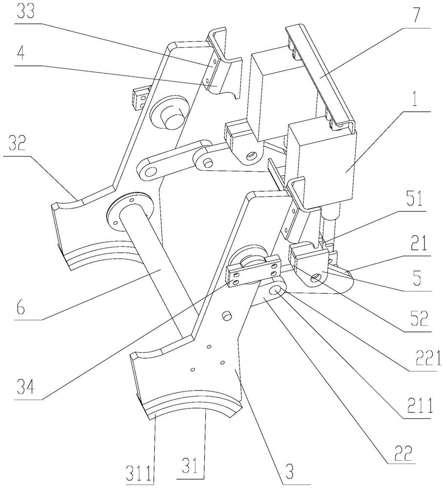
[0033] Such as Figure 1-5 As shown, a two-way locking mechanism for an axle includes a first executing part 1 , a locking part 3 , a stop seat 4 and a support 5 . in:

[0034] The first execution block 21 is hinged on the output end of the first execution part 1, and is used to drive the end of the first execution block 21 to rise and fall. Driven by the first execution part 1, the end of the first execution block 21 Follow up or down.

[0035] The first actuator 1 is a linear drive, which can use an electric push rod, and is an electric drive device that converts the rotational motion of the motor into the linear reciprocating motion of the push rod. It can be used as an executive machine in various simple or complex processes to realize remote control, centralized control or automatic control. It is a new type of linear actuator, which can be considered as an extension of the structure of the rotary motor.

[0036] A second execution block 22 is hinged between the middle...

Embodiment 2

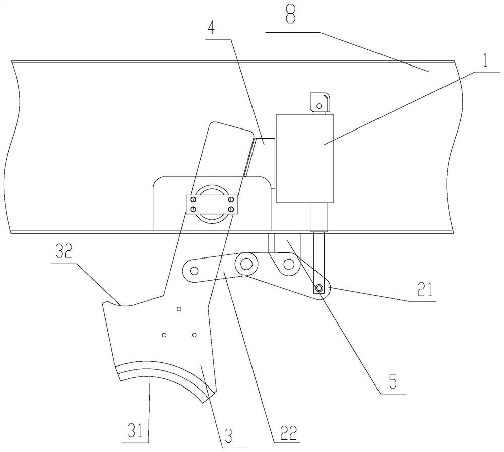
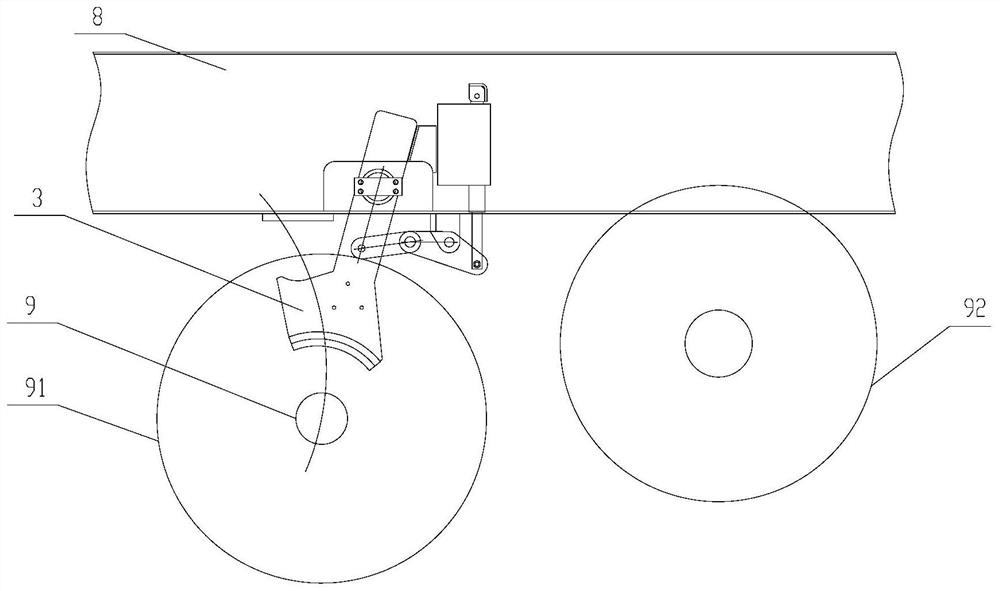
[0056] Such as Figure 1-5 As shown, based on the same inventive concept, the present invention also provides a road-rail transport vehicle, including the two-way locking mechanism of the above-mentioned axle, the vehicle beam 8 and the road axle 9, and the vehicle beam 8 is respectively connected with the locking part 3, the first The execution part 1 is hinged, and the stop seat 4 and the support 5 are respectively fixed on the vehicle beam 8. In addition to the two-way locking mechanism of the above-mentioned axle, the vehicle beam 8 and the road axle 9, the structure of other devices of the transport vehicle, For the connection relationship, installation location, etc., reference may be made to related publications in the prior art, and no further description will be made here.

[0057] Furthermore, when the locking portion 3 and the stopper seat 4 are opposed to each other, a supporting space 10 is formed between the vehicle beam 8 and the supporting position 32 , and the...


PUM


Abstract

The bidirectional locking mechanism comprises a first execution part, a stop seat, a support and a locking part, a second execution block is hinged between the middle of the locking part and a first execution block, and the locking part rotates along with the output end of the first execution part through the first execution block and the second execution block. The locking part is provided with an abutting position and a bearing position; the first execution part drives the locking part to abut against the stop seat, at the moment, the road axle is located below the abutting position so as to limit the road axle to continue to be recycled, and therefore the situation that railway wheels floor the ground and the road wheels fail during road driving is effectively avoided; when the highway-railway transport vehicle runs on the railway, the highway axle is limited by the bearing position, the highway wheels are effectively and stably prevented from falling, the driving safety is improved, and in the retraction process of the output end of the first execution part, the locking part is driven to be separated from the stop seat and separated from the moving path of the highway axle, so that the highway axle is switched in different states; and the operation convenience is improved.

Description

technical field [0001] The present application relates to the technical field of road-rail transport vehicles, in particular to a two-way locking mechanism for axles and road-rail transport vehicles. Background technique [0002] With the development of transportation capacity, cargo owners have higher and higher requirements for the timeliness of cargo delivery. The railways of various countries are constantly committed to improving the speed of cargo delivery, striving to form the speed advantage of cargo delivery, and gradually form container transportation. "Door to door" transportation. [0003] Due to the relatively late start, the development of the domestic transportation and logistics industry is relatively lagging behind, and the railway "door-to-door" transportation equipment is only used in the field of railway container transportation. However, railway container transportation has always been wandering between "door-to-station and station-to-door" transportatio...

Claims


Application Information

Patent Timeline
Patent Type & Authority Applications(China)
IPC IPC(8): B60B35/00B60F1/00
CPCB60B35/00B60F1/00Y02T30/00
Inventor 王全虎苏利杰刘爱文罗辉姚雄侯建云梅琨柯晓乐黄美林冯晔柏元强崔灿崔润哲
Owner CRRC YANGTZE GRP CO LTD
Why Eureka
Try Eureka