Pneumatic automatic return device

An automatic return and adjustment device technology, which is applied to switches with braking devices, buildings, door/window accessories, etc., can solve the problems of rotor and shaft falling off, affecting normal use, and different return speeds. High operation precision, wide application range, and smooth effect

Active Publication Date: 2021-06-29
WEIFANG ZHENGXIN PNEUMATIC TECH CO LTD
View PDF8 Cites 7 Cited by
  • Summary
  • Abstract
  • Description
  • Claims
  • Application Information

AI Technical Summary

Problems solved by technology

[0003] The rotor and shaft in the pneumatic floor spring in the prior art are of split structure. After the door is closed violently or used for a long time, the rotor and shaft of the split structure are prone to fall off, resulting in failure and affecting normal use; in addition, due to different Different doors have different weights, and the difference is large. Pneumatic floor springs of the same specification often lead to different return speeds of the doors, and even lighter doors return faster, while heavier doors cannot return normally. , needs external force to return to normal position

Method used


Image

  • Pneumatic automatic return device
  • Pneumatic automatic return device
  • Pneumatic automatic return device

Examples


Embodiment 1

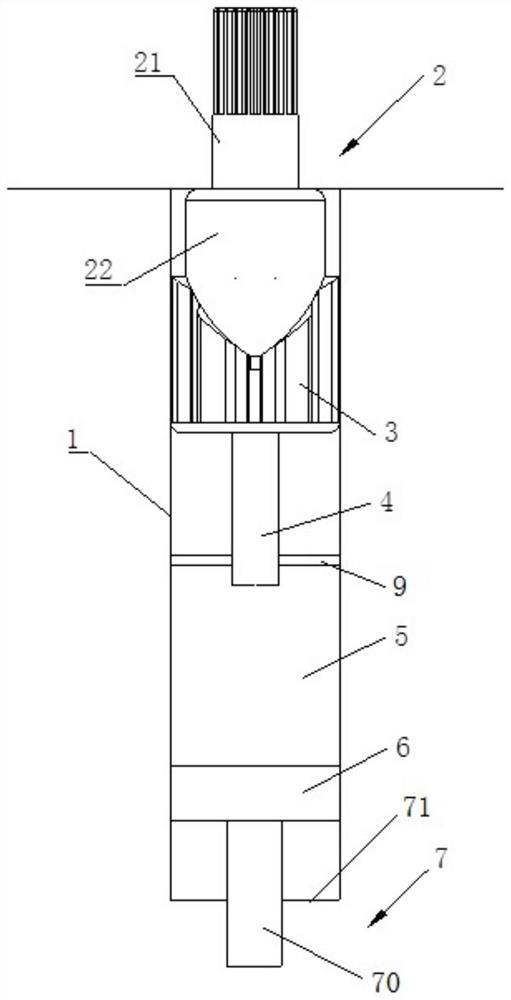
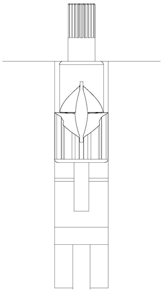
[0204] Such as figure 1 with figure 2 As shown, it is a schematic diagram of two different states of the pneumatic automatic return device of the present invention, and is a schematic diagram of two limit states, which is used to mount on the door, and the automatic return of the door is realized. At the time of installation, the rotation center of the door is mounted on the connecting shaft 21 of the upper convex shaft 2 in the drawing, and between the door and the connecting shaft 21 are synchronously rotated. figure 1 In the state shown, the door is closed, and when the door and the connecting shaft 21 rotate 90 °, it is figure 2 The state shown, the door is opened to the largest, after the door can be figure 2 Automatically returned in the state shown figure 1 The state shown, the automatic shutdown of the door is realized.

[0205] This embodiment first includes a hollow structure of the housing 1, the overall shape of the housing 1 is cylindrical, and the upper convex shaft ...


PUM


Abstract

The invention provides a pneumatic automatic return device. The problem that in the prior art, the return speeds of doors with different weights are different is solved. The pneumatic automatic return device comprises a shell, an upper convex shaft, a lower convex shaft, a piston, a sealed air chamber and an adjusting device, wherein the shell is of a hollow structure, the upper convex shaft is arranged in a gear sleeve, one end of the upper convex shaft extends outwards from the end part of the gear sleeve, the upper convex shaft only rotates in the gear sleeve, the lower convex shaft is also arranged in the gear sleeve and does reciprocating rectilinear motion only in the length direction of the gear sleeve, the upper convex shaft is in contact with the lower convex shaft, acting force always exists between the upper convex shaft and the lower convex shaft, the rotating motion of the upper convex shaft is synchronous with the rectilinear motion of the lower convex shaft, one end of the piston is used for continuously propping the lower convex shaft against the upper convex shaft, the sealed air chamber is a sealed cavity formed by an upper sealing piece and a lower sealing piece in the shell, high-pressure air is arranged in the sealed cavity, the other end of the piston extends into the sealed cavity, and the adjusting device is used for adjusting the volume of the sealing cavity.

Description

Technical field [0001] The present invention relates to doors, windows, and other fields requiring automatic return devices, and more particularly to a pneumatic automatic return device. Background technique [0002] Land spring, door closers and hydraulic hinges are automatic return closing devices commonly used in the current market. The floor spring is a hydraulic door, and its basic configuration is the sky axis and the ground (or the foot). The flax is connected to the upper part of the door frame and the door fan, which can be adjusted by a bolted bolt on the door fan. The plug-in shaft and a sleeve of the door can consist, the sky-axial floor axle can be applied to almost all wooden, steel, aluminum alloy doors and boundless glass doors using glass gates. [0003] The rotor and shaft in the pneumatic spring in the prior art are the split structure, and after a severe closed door or for a long time, the rotor and shaft of the split structure are prone to fall off, thereby f...

Claims


Application Information

Patent Timeline
Patent Type & Authority Applications(China)
IPC IPC(8): E05F3/04E05F3/22
CPCE05F3/04E05F3/22
Inventor 于宝峰司航卢波畅王梓赫
Owner WEIFANG ZHENGXIN PNEUMATIC TECH CO LTD
Why Eureka
Try Eureka