A camera optical axis pointing visual measurement method

A technology of visual measurement and optical axis pointing, applied in the field of robot vision, can solve the problems of time-consuming and laborious, can not guarantee the verticality of the main optical axis of the camera and the visual grasping plane, etc., to reduce workload and improve work efficiency.

Active Publication Date: 2022-07-22
SHENYANG SIASUN ROBOT & AUTOMATION
View PDF12 Cites 0 Cited by
  • Summary
  • Abstract
  • Description
  • Claims
  • Application Information

AI Technical Summary

Problems solved by technology

[0003] In the process of monocular vision positioning of machine vision, due to the artificial setting of the teaching point, the perpendicularity between the main optical axis of the camera and the visual grasping plane cannot be guaranteed. Therefore, if visual compensation is performed along the tool coordinate system, even if the tool coordinate system Parallel to the grasping plane, external parameters also need to be calibrated, which is very time-consuming and laborious for non-machine vision professionals

Method used


Image

  • A camera optical axis pointing visual measurement method
  • A camera optical axis pointing visual measurement method

Examples


Embodiment Construction

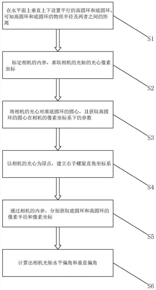
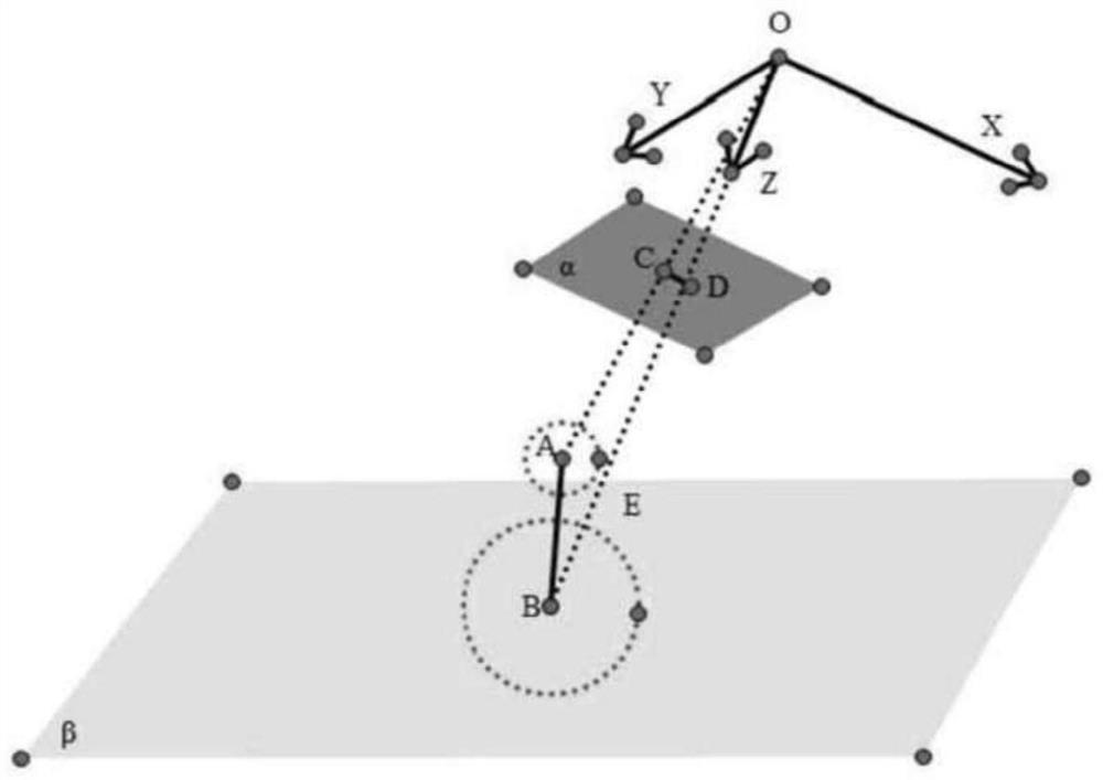
[0022] like figure 1 and figure 2 As shown, the present invention provides a camera optical axis pointing visual measurement method, comprising the following steps:

[0023] Step S1, set parallel high ring and bottom ring vertically up and down on the horizontal plane, it is known that the physical radius of the high ring and the bottom ring and the distance between them;

[0024] Step S2, calibrating the internal parameters of the camera, and obtaining the optical center pixel coordinates of the optical axis of the camera;

[0025] Step S3, align the optical center of the camera with the center of the bottom ring, and obtain the coordinates of the center of the high ring in the pixel coordinate system of the camera;

[0026] Step S4, establishing a right-handed spiral rectangular coordinate system with the optical center of the camera as the origin;

[0027] Step S5, obtain the pixel radius and pixel coordinates of the bottom ring and the high ring respectively through th...


PUM


Abstract

The invention relates to the field of robot vision, in particular to a visual measurement method for the pointing of the optical axis of a camera; Center pixel coordinates; then align the optical center of the camera with the center of the bottom ring, and obtain the coordinates of the center of the high ring in the pixel coordinate system of the camera; then use the optical center of the camera as the origin to establish a right-handed spiral rectangular coordinate system Obtain the pixel radius and pixel coordinates of the bottom ring and the high ring respectively; finally calculate the horizontal declination and vertical declination of the optical axis of the camera; the present invention enables the user to realize that the optical axis of the camera is perpendicular to a certain plane through simple operations , so that the horizontal physical offset between any pixel point and the optical axis can be obtained without calibrating the external parameters of the camera. When the robot teaching operation related to visual positioning is implemented, the workload of the user can be greatly reduced and the work efficiency can be improved. .

Description

technical field [0001] The invention relates to the field of robot vision, in particular to a visual measurement method for pointing the optical axis of a camera. Background technique [0002] Visual measurement technology has the principle advantages of non-contact, high precision, strong real-time performance and rich information, and is widely used in the fields of automatic navigation, medical diagnosis, military reconnaissance and human-computer interaction. Especially in the field of advanced equipment manufacturing, visual measurement can provide important assistance and guidance for the assembly line processing, automated assembly, product quality inspection and other links in the industrial field. [0003] In the process of monocular vision positioning of machine vision, due to the artificial setting of the teaching point, the perpendicularity of the main optical axis of the camera and the visual grasping plane cannot be guaranteed. Therefore, if visual compensation...

Claims


Application Information

Patent Timeline
Patent Type & Authority Patents(China)
IPC IPC(8): G01B11/26G01C11/00
CPCG01B11/26G01C11/00
Inventor 陈亮曲道奎王晓东姜楠徐佳新李此君
Owner SHENYANG SIASUN ROBOT & AUTOMATION
Why Eureka
Try Eureka