High-precision micro-displacement actuator utilizing threaded parallel structure

A high-precision, parallel technology, applied in the field of lithography machines, can solve the problems of unavoidable displacement output backlash, complex displacement actuator structure, limited stroke amplification capability, etc., to achieve convenient design and processing, simple structure, and improved output. The effect of precision

Active Publication Date: 2021-06-29
NANJING INST OF ASTRONOMICAL OPTICS & TECH NAT ASTRONOMICAL OBSE
View PDF8 Cites 1 Cited by
  • Summary
  • Abstract
  • Description
  • Claims
  • Application Information

AI Technical Summary

Problems solved by technology

[0004] Due to the complex structure of the coarse and fine combined platform type displacement actuator, the inchworm motor designed by the piezoelectric material using the "inchworm principle" has a large stroke and high precision. High, and can be self-locking when power is off, but the current market price is relatively high, and the domestic technology of this type of product is not yet mature, and for the micro-displacement actuator mechanism that uses the displacement amplification mechanism to amplify the stroke of the piezoelectric material, usually Under normal circumstances, the maximum expansion and contraction of the piezoelectric material per 1 millimeter of length is about 1 micron. Therefore, in order to improve the stroke range of the piezoelectric displacement actuator, although the displacement amplification mechanism is used, the stroke amplification capability is very limited, and at the same time Piezoelectric materials need to be continuously powered
However, for the commonly used reducer plus precision screw structure to achieve micro-displacement output, there is a gap in the transmission of gears or worm gears, and it is inevitable that there will be a gap in the displacement output, which limits its final displacement output accuracy.

Method used


Image

  • High-precision micro-displacement actuator utilizing threaded parallel structure

Examples


Embodiment 1

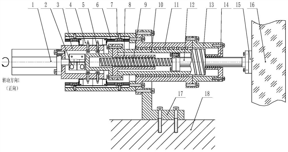
[0023] Such as figure 1 As shown, a high-precision micro-displacement actuator using a threaded parallel structure in this implementation includes two sets of parallel threaded screw structures, that is, the parallel threaded screw structure refers to the first threaded screw (9) and The first screw nut (8) is placed inside the second threaded screw (10) (hollow). Specifically, the actuator includes a first threaded screw 9 and a second threaded screw 10 (hollow), the first threaded screw 9 and the second threaded screw 10 (hollow) have the same helical direction and have different leads , that is, the first threaded screw (lead P1) and the second threaded screw (lead P2), and the output of the displacement is realized by using the relative lead difference between the first threaded screw and the second threaded screw. The first threaded screw 9 is connected to the mirror 16 through the rolling spline shaft 12 , and the first screw nut 8 matched with the first threaded screw ...


PUM


Abstract

The invention discloses a high-precision micro-displacement actuator utilizing a threaded parallel structure, which comprises two sets of parallel threaded screw rod structures, namely a first threaded screw rod and a first screw rod nut matched with the outside, and a second threaded screw rod with a hollow structure and a second screw rod nut matched with the outside, the first threaded lead screw and the second threaded lead screw are the same in spiral direction and have different thread leads, displacement output is achieved through the relative lead difference between the first threaded lead screw and the second threaded lead screw, the first threaded lead screw is connected with the mirror face through the guide rod, the first lead screw nut and the second threaded lead screw are both connected with the motor, and the second lead screw nut is fixed to a telescope rack. The actuator is mainly used for accurately adjusting the position of the optical mirror surface in the field of astronomical telescopes, and the mirror surface is continuously displaced without a gap or backlash phenomenon when the position of the mirror surface is adjusted. The position adjustment precision of the mirror surface can reach a submicron level or even a nanometer level.

Description

technical field [0001] The invention relates to a precise mirror position adjustment device, in particular to a high-precision micro-displacement actuator. It is mainly used in the position adjustment of the optical mirror of astronomical telescopes, and is also suitable for other fields that require ultra-high precision control of the position of certain structural parts, such as the field of lithography machines. Background technique [0002] In order to reduce the cost and obtain good image quality, large-scale astronomical telescopes mostly use splicing mirror active optical technology, applying modern sensing and control technology, and splicing small-scale sub-mirrors into large-caliber mirrors. The micro-displacement actuator is a precise displacement output device, which completes the positioning, support and adjustment of the sub-mirror in the splicing mirror active optical technology. It must have high resolution, high stability, high stiffness, and high repeatabil...

Claims


Application Information

Patent Timeline
Patent Type & Authority Applications(China)
IPC IPC(8): G02B7/183G02B7/198
CPCG02B7/183G02B7/198
Inventor 牛冬生
Owner NANJING INST OF ASTRONOMICAL OPTICS & TECH NAT ASTRONOMICAL OBSE
Why Eureka
Try Eureka