Isolating switch mechanical locking device

A technology of locking device and isolating switch, which is applied in the direction of air switch parts, etc., can solve the problems of long transmission rod, rough processing and requirements of transmission parts, and easy bending of rods, etc.

Pending Publication Date: 2021-06-29
西安西电高压开关有限责任公司 +1
View PDF0 Cites 0 Cited by
  • Summary
  • Abstract
  • Description
  • Claims
  • Application Information

AI Technical Summary

Problems solved by technology

Generally, the mechanical locking device only requires no obstruction during operation, and the processing and requirements of the transmission parts are relatively rough. Due to the influence of the environment and other factors during use, it is easy to get stuck or the parts are damaged.
Especially when the distance between the main knife of the isolating switch and the ground knife of the grounding switch is far away, a long-distance lock is formed. The transmission rod of this kind of lock is long, and the rod is easy to bend due to its own weight.
[0005] The locking plate of the existing locking device is a flat plate with holes, and the locking plate is worn on the shaft. The thickness of the plate is generally much smaller than the length and width. When the parts are heat treated or subjected to large forces and moments during the action process, the locking plate is easy. Deformation causes stagnation, which in turn causes the locking process to fail to be achieved smoothly
[0006] In particular, when the power source of the isolating switch and the grounding switch are far away, the length of the transmission rod (pull rod) of the locking device is relatively long, and the transmission rod is easily bent and deformed by its own gravity during long-term operation. All adopt fixed connection, the bending of the transmission rod will cause the end locking plate to warp, causing the locking project to be stuck or the locking action cannot be realized
[0007] In addition, the locking plate in the prior art generally adopts an elongated shaft hole or rollers installed at both ends of the locking plate as a guide. If it is too large or too small, the locking plate will rotate in addition to the linear motion, which will increase the transmission resistance; if it is too small, the locking plate will have no room for movement due to the low precision of the locking device parts, and it is easy to get stuck
[0008] In addition, in order to eliminate the locking stagnation caused by the bending of the transmission rod, support structures are added at both ends of the transmission rod, which increases the complexity of the locking device, and the added parts also increase the cost of the locking structure

Method used


Image

  • Isolating switch mechanical locking device
  • Isolating switch mechanical locking device
  • Isolating switch mechanical locking device

Examples


Embodiment Construction

[0044]In order to make the purposes, technical solutions and advantages of the embodiments of the present invention clearer, the technical solutions in the embodiments of the present invention will be clearly and completely described below with reference to the accompanying drawings in the embodiments of the present invention. Obviously, the described embodiments These are some embodiments of the present invention, but not all embodiments. Based on the embodiments of the present invention, all other embodiments obtained by those of ordinary skill in the art without creative efforts shall fall within the protection scope of the present invention.

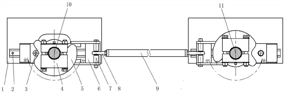
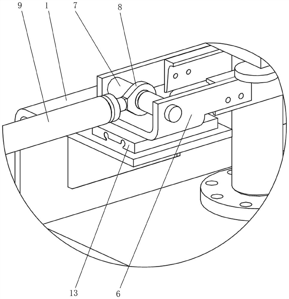
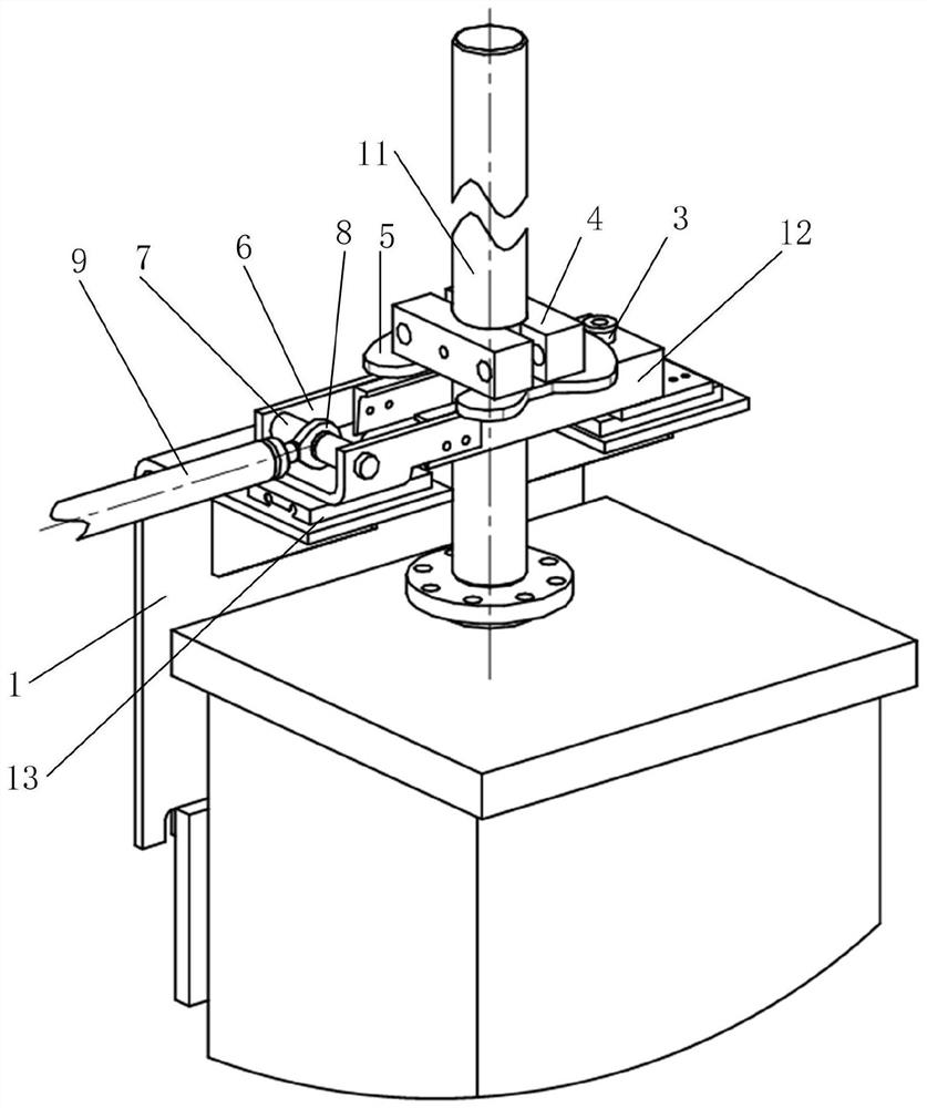
[0045] Please refer to Figure 1 to Figure 4 , figure 1 It is a schematic structural diagram of the application of the mechanical locking device of the isolation switch provided by the embodiment of the present invention; figure 2 A schematic diagram of a partial structure of a mechanical locking device for an isolation switch pro...


PUM


Abstract

The invention discloses an isolating switch mechanical locking device. When an isolating switch is about to be switched on, a locking disc rotates clockwise, a rolling wheel is pushed by the locking disc to move leftwards and move out of a second groove, a supporting frame on the side of a grounding switch is driven by a transmission rod to move leftwards, a roller on a grounding switch side enters the second groove of the locking disc until the isolating switch is closed to the end, the roller on the grounding switch side is clamped in the second groove of the locking disc on the grounding switch side, the locking disc on the grounding switch side cannot rotate, the grounding switch cannot be closed, and if the grounding switch needs to be closed, the isolating switch must be opened firstly. And vice versa, mutual locking of the isolating switch and the grounding switch is realized. The transmission rod is connected with a pin shaft through a knuckle bearing, and when the transmission rod is bent, a corner caused by bending of the transmission rod is released by rotation of the knuckle bearing, so that the locking action is not affected by bending of the transmission rod caused by self weight, and the dependence on the machining precision of parts such as a guide part is low.

Description

technical field [0001] The present invention relates to the technical field of electrical equipment, in particular to a mechanical locking device of an isolation switch. Background technique [0002] With the continuous improvement of power equipment technology, the requirements for power equipment are also getting higher and higher. The power sector has gradually strengthened the anti-misoperation management, requiring that a mechanical locking device must be installed between the isolating switch and the grounding switch. [0003] Mechanical locking is a mechanical transmission structure for outdoor use, and the operating environment is relatively harsh: wind, frost, rain and snow, high temperature exposure, low temperature and severe cold, high humidity, salt spray, etc. In addition, the precision of the transmission parts of the locking device is generally low, so it is often widely used. Problems such as sticking and rusting of parts occurred in the use site. [0004]...

Claims


Application Information

Patent Timeline
IPC IPC(8): H01H31/10
CPCH01H31/10
Inventor 杨颖彭云成冯艳周昊明冯亮亮
Owner 西安西电高压开关有限责任公司
Why Eureka
Try Eureka