
Display panel, brightness compensation method and display device

A display panel and brightness compensation technology, applied in the field of display panels and display devices, can solve problems such as huge equipment, achieve the effect of avoiding brightness differences and improving visual experience

Active Publication Date: 2021-06-29
BOE TECH GRP CO LTD
View PDF6 Cites 2 Cited by
  • Summary
  • Abstract
  • Description
  • Claims
  • Application Information

AI Technical Summary

Problems solved by technology

However, the current optical compensation technology uses a CCD camera to collect the brightness of each pixel to compensate. This method requires relatively large equipment, so it is limited to one-time compensation before the manufacturer ships, and cannot address the brightness difference caused by long-term product aging. make compensation

Method used


Image

  • Display panel, brightness compensation method and display device
  • Display panel, brightness compensation method and display device
  • Display panel, brightness compensation method and display device

Examples


Embodiment Construction

[0036] Embodiments of the present application are described in detail below, examples of which are shown in the drawings, wherein the same or similar reference numerals denote the same or similar elements or elements having the same or similar functions throughout. The embodiments described below by referring to the figures are exemplary, are only for explaining the present application, and should not be construed as limiting the present application.

[0037] In the description of the present application, it should be understood that the terms "center", "longitudinal", "transverse", "length", "width", "thickness", "upper", "lower", "front", " Orientation indicated by rear, left, right, vertical, horizontal, top, bottom, inside, outside, clockwise, counterclockwise, etc. The positional relationship is based on the orientation or positional relationship shown in the drawings, which is only for the convenience of describing the application and simplifying the description, and doe...


PUM

PropertyMeasurementUnit
thicknessaaaaaaaaaa

Abstract

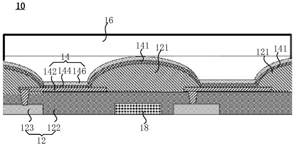
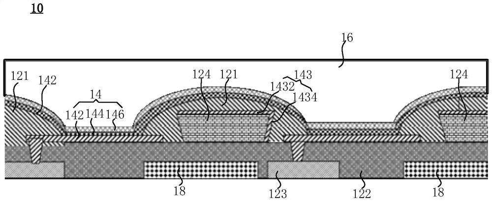
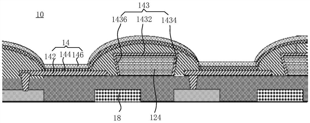
The invention provides a display panel, a brightness compensation method and a display device. The display panel comprises an array substrate, a light-emitting layer, a plurality of optical film layers and a photoelectric sensor. The light-emitting layer is located on one side of the array substrate, the array substrate is used for driving the light-emitting layer to emit light, the optical film layers are located on the side, away from the array substrate, of the light-emitting layer, and light emitted by the light-emitting layer forms waveguide light on the array substrate and / or the optical film layers. The photoelectric sensor is used for obtaining the waveguide light so as to perform brightness compensation on light emitted by the light-emitting layer according to data of the waveguide light. According to the display panel provided by the invention, the waveguide light formed by the light emitted by the light-emitting layer on the array substrate or the optical film layers can be obtained through the arrangement of the photoelectric sensor so that the brightness compensation can be performed on the light emitted by the corresponding light-emitting layer according to the brightness of the waveguide light, and the brightness uniformity of the display panel is ensured; and the visual experience of the display panel is improved.

Description

technical field [0001] The present application relates to the display field, and in particular to a display panel, a brightness compensation method and a display device. Background technique [0002] Organic light-emitting diode display (Organic Light-Emitting Diode, OLED) is a self-luminous display device that emits light through OLED to display images. It is thinner and lighter than liquid crystal display (LCD), and has higher display characteristics. It is attracting much attention as a next-generation display device for portable electronic devices. [0003] Generally, the active driving method of OLED devices adopts voltage driving. For voltage-driven compensation methods, it can be divided into electrical compensation and optical compensation. Among them, optical compensation directly uses brightness as the compensation object. After compensation, it can achieve the advantages of uniform brightness and height. Therefore, optical compensation is given high hopes and is ...

Claims


Application Information

Patent Timeline
Patent Type & Authority Applications(China)
IPC IPC(8): H01L27/32H01L51/52G02F1/1523G02F1/1524G02F1/153G02F1/163G09G3/3258
CPCG02F1/1523G02F1/15245G02F1/153G02F1/163G09G3/3258G09G2320/0233H10K59/60H10K59/122H10K59/878G09G3/3225G09G2320/029G09G2360/145H10K59/13G09G2360/16H10K50/856H10K2102/00
Inventor 樊星孔超温向敏
Owner BOE TECH GRP CO LTD
Learn More