
Display panel

A display panel and display area technology, which is applied to semiconductor devices, electrical components, circuits, etc., can solve problems that affect the normal operation of optical components and optical components cannot receive optical signals, so as to improve imaging effects, display effects, and transparency. The effect of light rate

Active Publication Date: 2021-06-29
WUHAN CHINA STAR OPTOELECTRONICS SEMICON DISPLAY TECH CO LTD
View PDF3 Cites 15 Cited by
  • Summary
  • Abstract
  • Description
  • Claims
  • Application Information

AI Technical Summary

Problems solved by technology

[0004] The embodiment of the present application provides a display panel to solve the problem that the optical elements arranged under the screen cannot receive sufficient light signals and affect the normal operation of the optical elements

Method used


Image

  • Display panel
  • Display panel
  • Display panel

Examples


Embodiment Construction

[0043] The following will clearly and completely describe the technical solutions in the embodiments of the application with reference to the drawings in the embodiments of the application. Apparently, the described embodiments are only some of the embodiments of the application, not all of them. Based on the embodiments in this application, all other embodiments obtained by those skilled in the art without making creative efforts belong to the scope of protection of this application. In addition, it should be understood that the specific implementations described here are only used to illustrate and explain the present application, and are not intended to limit the present application. In this application, unless stated to the contrary, the used orientation words such as "up" and "down" usually refer to up and down in the actual use or working state of the device, specifically the direction of the drawing in the drawings ; while "inside" and "outside" refer to the outline of ...


PUM


Abstract

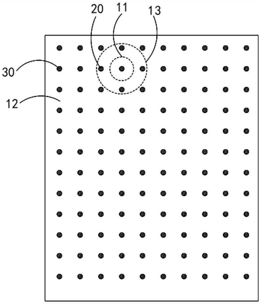
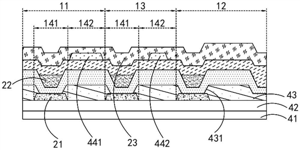
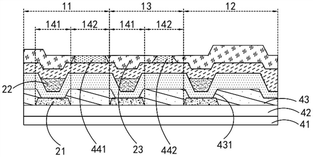
The embodiment of the invention discloses a display panel. The display panel comprises a first display area, a third display area and a second display area which are sequentially and adjacently arranged. The display panel comprises a substrate, a pixel definition layer and an inhibition layer, wherein the pixel definition layer and the inhibition layer are sequentially arranged on one side of the substrate; a gap area is arranged between two adjacent pixel openings on the pixel definition layer, and the inhibition layer is located in the gap area; the inhibition layer comprises a first cathode inhibition layer located in the first display area and a second cathode inhibition layer located in the third display area; and the ratio of the area of the orthographic projection of the second cathode inhibition layer on the substrate to the area of the third display area is smaller than the ratio of the area of the orthographic projection of the first cathode inhibition layer on the substrate to the area of the first display area. By arranging the third display area playing a transition role, on the premise that the light transmittance of the first display area is improved through the inhibition layer, the brightness difference of all the display areas is reduced, and therefore the display effect is improved.

Description

technical field [0001] The present application relates to the field of display technology, in particular to a display panel. Background technique [0002] OLED (Organic Light Emitting Diode, Organic Light Emitting Diode) display technology has attracted more and more attention from scientific researchers, and is widely used in display fields such as mobile phones, tablets, and TVs. With the rapid development of display devices, users The screen-to-body ratio requirements of display devices are getting higher and higher, making large-size and high-resolution comprehensive display devices a future development direction. [0003] In the existing technology, in order to increase the screen-to-body ratio as much as possible, optical components such as the front camera and face recognition are usually placed under the screen. However, in the existing OLED full-scale display device, the cathode is set on the entire surface. , while the transmittance of the cathode for light is low...

Claims


Application Information

Patent Timeline
Patent Type & Authority Applications(China)
IPC IPC(8): H01L51/52H01L27/32
CPCH10K59/122H10K50/82H10K50/84
Inventor 吕磊金蒙袁涛黄金昌
Owner WUHAN CHINA STAR OPTOELECTRONICS SEMICON DISPLAY TECH CO LTD
Learn More