Check patentability & draft patents in minutes with Patsnap Eureka AI!

Conductive terminal structure

A technology of conductive terminals and terminals, applied in the direction of contact parts, etc., can solve the problems of thickening the elastic arm of the power terminal and reducing the elasticity of the elastic arm, and achieve the effect of reducing heat and accelerating wear

Inactive Publication Date: 2021-06-29
ELECTRIC CONNECTOR TECH
View PDF6 Cites 0 Cited by
  • Summary
  • Abstract
  • Description
  • Claims
  • Application Information

AI Technical Summary

Problems solved by technology

[0003] Prior art 1 (CN209298421U) discloses a connector, including a metal shell, an insulating shell, a shielding shrapnel, a clamping assembly and a terminal, in order to make the terminal of the connector suitable for a larger current for fast charging In the environment, the usual practice is to use thicker conductive materials, but the thickening of the material makes the elastic force arm of the power terminal thicker, reduces the elasticity of the elastic force arm, and accelerates the wear of the contact part of the terminal

Method used


Image

  • Conductive terminal structure
  • Conductive terminal structure
  • Conductive terminal structure

Examples


Embodiment Construction

[0032] In order to make the above objects, features and advantages of the present invention more comprehensible, specific implementations of the present invention will be described in detail below in conjunction with the accompanying drawings. In the following description, numerous specific details are set forth in order to provide a thorough understanding of the present invention. However, the present invention can be implemented in many other ways different from those described here, and those skilled in the art can make similar improvements without departing from the connotation of the present invention, so the present invention is not limited by the specific implementations disclosed below.

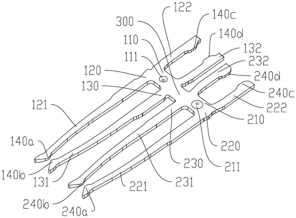
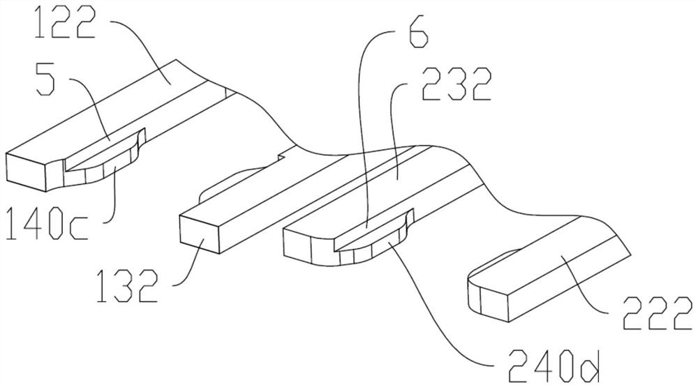
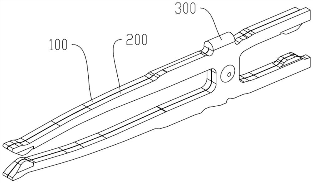
[0033] Such as Figure 1 to Figure 4 As shown, a conductive terminal structure includes a first terminal 100 and a second terminal 200 electrically connected to the first terminal, at least one second terminal 200; wherein, the first terminal 100 includes a second terminal 200 A main...


PUM


Abstract

The invention discloses a conductive terminal structure. The structure comprises: a first terminal and at least one second terminal electrically connected with the first terminal. The first terminal comprises: a first main body and a second main body, a first elastic upper arm; and a first elastic lower arm, wherein the first elastic upper arm and the first elastic lower arm are respectively provided with a first contact part. The second terminal comprises: a second main body which is fixedly connected with the first main body; a second elastic upper arm; and a second elastic lower arm, wherein the second elastic upper arm and the second elastic lower arm are respectively provided with a second contact part. Compared with the prior art, the conductive terminal structure can be applied to a rapid charging environment, and the abrasion of the contact part of the conductive terminal cannot be accelerated.

Description

technical field [0001] The invention relates to the technical field of electrical connection, in particular to a conductive terminal structure applied to a USB Type-C connector. Background technique [0002] The USB connector includes a male seat and a female seat. The female seat is installed in an electronic device such as a mobile phone. The male seat is inserted into the female seat from the outside of the electronic device, so that the electronic device performs data transmission or power transmission with external devices through the USB connector. Nowadays, the charging current of mobile phones is getting larger and larger. When the internal impedance of the USB connector (male or female) rises, a lot of heat will be generated during charging (the relationship between heat and current is Q=I2*R *t, where I is current, R is impedance, and t is time). When the heat generated is greater than the heat dissipated, the temperature inside the USB connector increases. [00...

Claims


Application Information

Patent Timeline
Patent Type & Authority Applications(China)
IPC IPC(8): H01R13/02
CPCH01R13/02
Inventor 邬彬彭君兰毕伟陈伟华
Owner ELECTRIC CONNECTOR TECH
Features
  • R&D
  • Intellectual Property
  • Life Sciences
  • Materials
  • Tech Scout
  • Unparalleled Data Quality
  • Higher Quality Content
  • 60% Fewer Hallucinations
Learn More