Electric connector

A technology for electrical connectors and electrical connections, applied in connection, electrical solid devices, circuits, etc., can solve the problems of low alignment accuracy, complex connection structure, unfavorable material saving, etc., and achieve the effect of improving alignment accuracy

Active Publication Date: 2021-06-29
FOXCONN (KUNSHAN) COMPUTER CONNECTOR CO LTD +1
View PDF4 Cites 1 Cited by
  • Summary
  • Abstract
  • Description
  • Claims
  • Application Information

AI Technical Summary

Problems solved by technology

[0002] U.S. Patent Publication No. US8998623B2 discloses an electrical connector, which includes two insulative bodies close together, terminals held on the insulative bodies, a cover mounted above the insulative bodies, and two The cover is thus a clasp that connects the two insulating bodies together. The cover is provided with arms extending laterally. The clasp can be buckled on the arms of the two covers at the same time to connect the two insulating bodies Combined together, the electrical connector can be welded on the board at one time; however, the above-mentioned connection structure of the electrical connector is relatively complicated, which is not conducive to saving materials, and the arm is not provided with a lateral limit for the buckle Therefore, the gap between the two insulating bodies after assembly may be different in size, which not only easily leads to low alignment accuracy between the terminal and the chip module, but also leads to failure to meet the inherent assembly requirements of the electrical connector. Size requirements

Method used


Image

  • Electric connector
  • Electric connector
  • Electric connector

Examples


Embodiment Construction

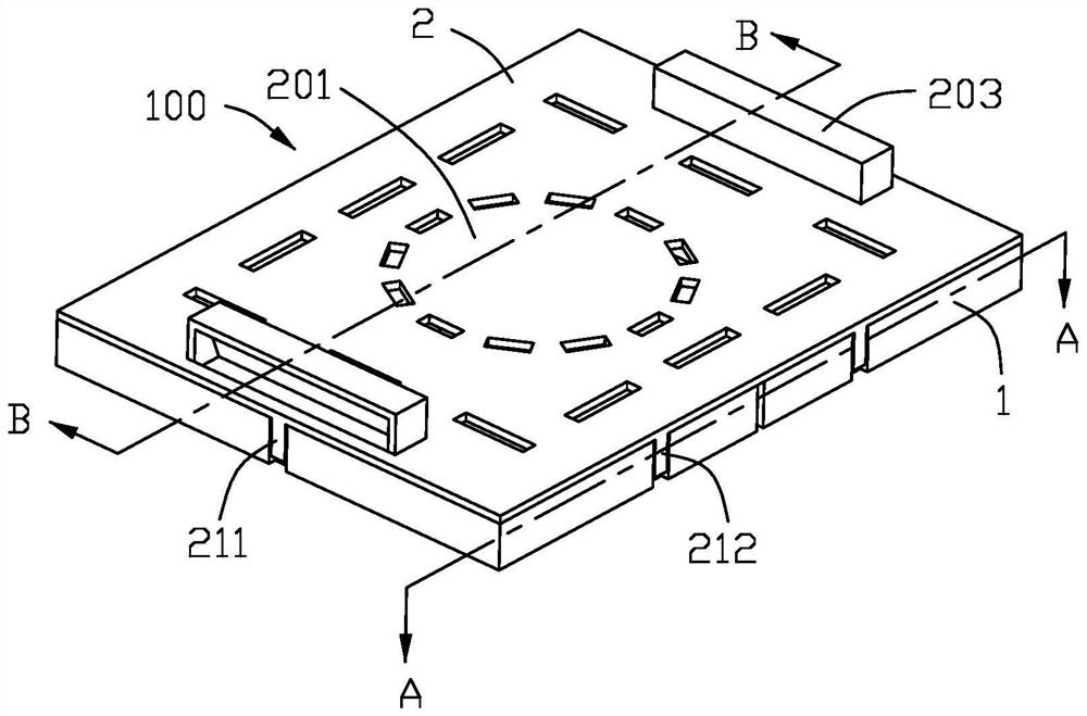
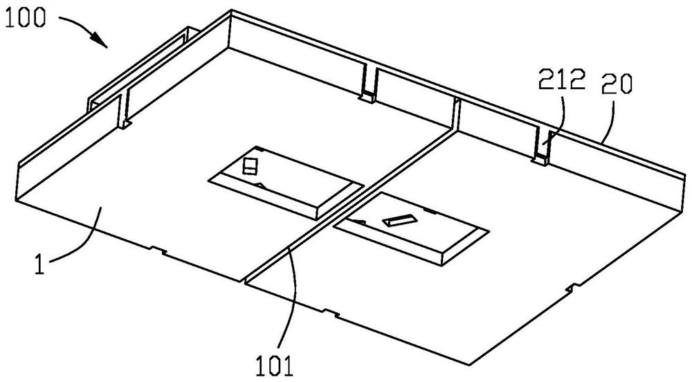
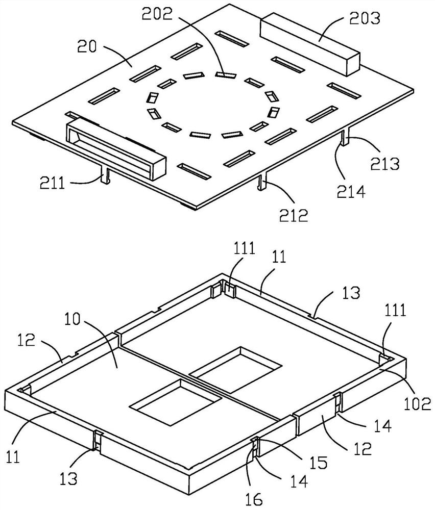
[0039] Below, will combine Figure 1 to Figure 7 The specific implementation manner of the electrical connector of the present invention is introduced.

[0040] Such as Figure 1 to Figure 7 As shown, the present invention provides an electrical connector 100 for electrically connecting a chip module (not shown), the electrical connector 100 includes two base units 1 and a pickup cover 2, each The seat unit 1 holds a plurality of terminals (not shown), and the two seat units 1 are independently arranged and spliced ​​together side by side along a longitudinal direction to jointly form a shelter for a shelter. The accommodating groove 10 of the chip module, the terminals protrude into the accommodating groove 10 so as to be connected with the chip module, specifically, some of the terminals are connected with a plurality of conductive sheets on the chip module. One-to-one contact, so different relative positions between the terminals and the chip module will affect their alig...


PUM


Abstract

The invention discloses an electric connector. The electric connector is used for being electrically connected with a chip module, the electric connector comprises two seat body units and a pickup cover, and each seat body unit is fixedly provided with a plurality of terminals. The two seat body units are independently arranged and are spliced together side by side along a lengthwise direction so as to jointly define an accommodating groove for accommodating the chip module, and the terminal convexly extends into the accommodating groove so as to be in butt joint with the chip module; and a gap is reserved between the two seat body units, the two seat body units are aligned with each other in the transverse direction perpendicular to the lengthwise direction, and the pickup cover comprises a platform part and a plurality of buckles, wherein the platform part integrally extends and covers the two seat body units at the same time, and the buckles extend downwards from the platform part and buckle the two seat body units at the same time. According to the invention, the integrated pickup cover covers the two split seat body units at the same time, so that the two seat body units can be relatively positioned, unified plate feeding and welding can be realized, and the alignment precision of the terminal and the chip module can be improved.

Description

【Technical field】 [0001] The invention relates to an electrical connector, in particular to an electrical connector installed on a circuit board to electrically connect a chip module. 【Background technique】 [0002] U.S. Patent Publication No. US8998623B2 discloses an electrical connector, which includes two insulative bodies close together, terminals held on the insulative bodies, a cover mounted above the insulative bodies, and two The cover is thus a clasp that connects the two insulating bodies together. The cover is provided with arms extending laterally. The clasp can be buckled on the arms of the two covers at the same time to connect the two insulating bodies Combined together, the electrical connector can be welded on the board at one time; however, the above-mentioned connection structure of the electrical connector is relatively complicated, which is not conducive to saving materials, and the arm is not provided with a lateral limit for the buckle Therefore, the ...

Claims


Application Information

Patent Timeline
Patent Type & Authority Applications(China)
IPC IPC(8): H01R33/74H01R13/502H01R13/52H05K3/34
CPCH01R33/74H01R13/502H01R13/5213H05K3/341H01L23/544H01L2223/54426H01L2223/54486H01L23/053H01L21/4803H01L23/4093H01R12/716H01R12/7017H01R13/514
Inventor 郑善雍
Owner FOXCONN (KUNSHAN) COMPUTER CONNECTOR CO LTD
Why Eureka
Try Eureka