Cleaning method of lithium battery coating die

A lithium battery and coating technology, which is applied to the device, coating, spraying device and other directions for coating liquid on the surface, which can solve the problem of inconsistent positioning and disassembly of the die head position, decreased consistency of coated products, and coated pole pieces. Scrap and other problems, to solve the problem of coating commissioning scrap, improve cleaning and maintenance efficiency, and avoid installation and positioning.

Active Publication Date: 2022-05-03
HEFEI GUOXUAN HIGH TECH POWER ENERGY
View PDF8 Cites 0 Cited by
  • Summary
  • Abstract
  • Description
  • Claims
  • Application Information

AI Technical Summary

Problems solved by technology

[0004] Reassembly after disassembling the die head will bring a series of problems, such as: the gap between the die lip and the back roller changes after the die head is assembled, the gap between the upper and lower die lips of the die lip changes, and the position of the die sheet changes, etc., which will cause the position of the die head to change. The repeated positioning of the product is inconsistent with that before disassembly, which leads to changes in the width and thickness of the coated product, which cannot meet the requirements of the product manufacturing process; the process debugging causes poor coating products and a decrease in the consistency of the coated products, resulting in the scrapping of the coated pole pieces. Reduced process product yield and efficiency, increased process material consumption and manufacturing costs

Method used


Image

  • Cleaning method of lithium battery coating die
  • Cleaning method of lithium battery coating die

Examples


Embodiment 1

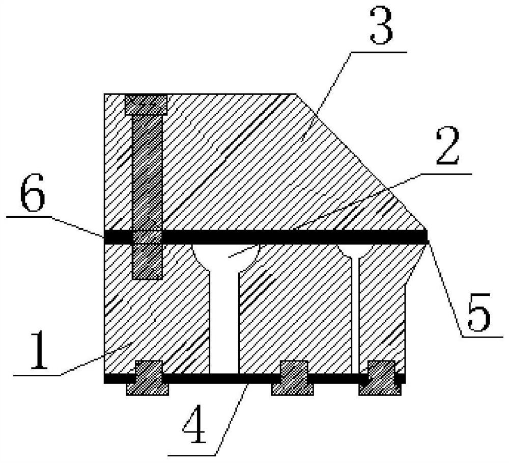
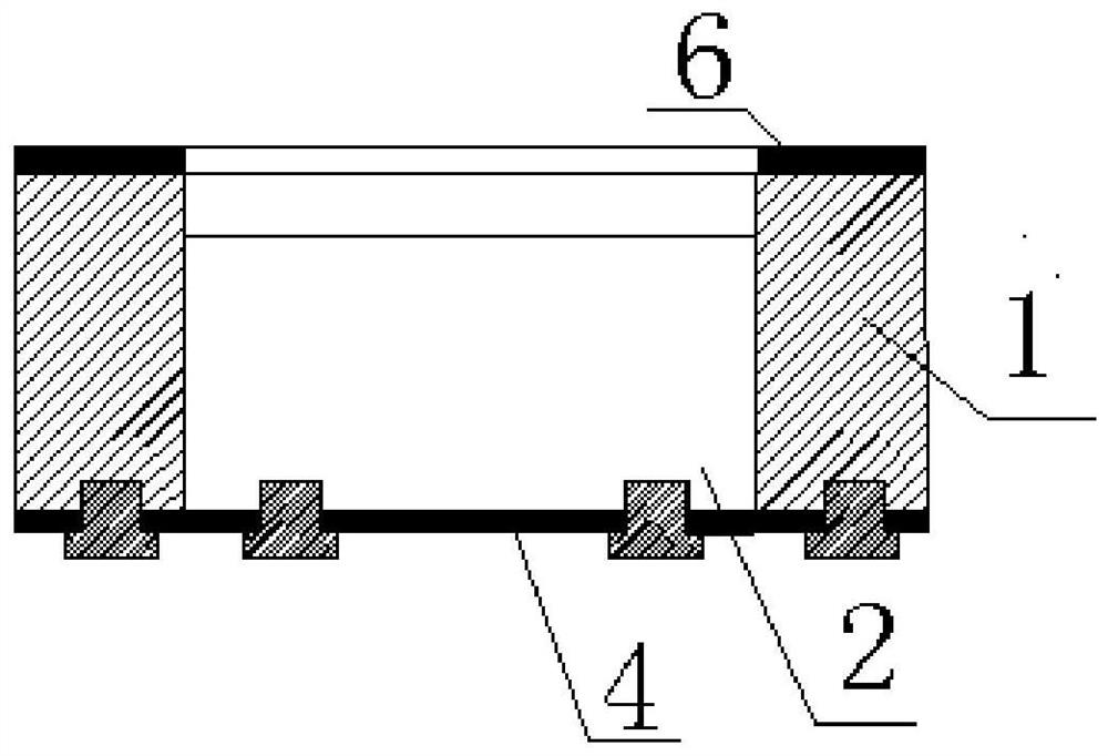
[0022] Such as figure 1 , figure 2 As shown, the lithium battery coating die head includes a lower die 1 , a cavity 2 , an upper die 3 , a cavity sealing plate 4 , a coating port 5 , a feed port (not shown in the figure), and a coating die 6 .

[0023] At least one material chamber 2 is opened on the lower mold 1, and the material chamber 2 is used to store the slurry used for coating. Setting a plurality of material chambers 2 can ensure that the flow rate of the slurry in the coating process meets the demand. The top runs through to the bottom, and the material cavity is a strip-shaped cavity whose length direction is along the left-right direction of the lower die 1 .

[0024] The material cavity 2 includes an upper cavity and a lower cavity, the upper cavity is the part from the top opening of the material cavity 2 to the middle of the material cavity 2, and the lower cavity is the part from the middle of the material cavity 2 to the material cavity 2 The bottom of the ...

Embodiment 2

[0031] The difference between this embodiment and Embodiment 1 is that the cleaning method of the lithium battery coating die head also includes the following steps: after the cavity sealing plate 4 is removed, the coating port 5 is blocked, and the feeding system passes through the feeding The mouth continues to supply material to the material cavity 2, so that the internal pressure of the material cavity 2 increases, and the residual slurry in the material cavity 2 is extruded by the new slurry and discharged from the bottom opening of the material cavity 2.


PUM


Abstract

The invention discloses a cleaning method for a lithium battery coating die, and relates to the technical field of lithium battery coating. The lithium battery coating die includes a lower mold, a material cavity, an upper mold, a cavity sealing plate, a coating port, and a feeding mouth; the lower mold is provided with at least one material cavity, and the material cavity penetrates from the top of the lower mold to the bottom; the upper mold is fixedly connected to the top of the lower mold and closes the top of the material cavity opening; the cavity sealing plate is detachably fixedly connected to the bottom of the lower mold and closes the bottom opening of the material cavity; the gap between the front side of the upper mold and the front side of the lower mold forms a coating Cloth mouth, the rear side of the lower mold is provided with a feed port, and the coating port, material cavity, and feed port are sequentially connected from front to back. The invention has the advantages that the material cavity can be cleaned without disassembling the upper mold and the lower mold, which ensures that the mechanical installation accuracy and mechanical positioning accuracy of the die head do not change after cleaning the material cavity.

Description

technical field [0001] The invention relates to the technical field of lithium battery coating, in particular to a cleaning method for a lithium battery coating die. Background technique [0002] As a clean power source, lithium-ion batteries have been widely used in digital, electric tools, electric bicycles, electric vehicles and other fields. The lithium battery market is widely used, and the demand for production capacity is high. The degree of automation of the complex lithium battery manufacturing process is constantly improving to improve product manufacturing efficiency and reduce product manufacturing costs. The coating process is an important process in the production process of lithium batteries. After high-speed and long-term coating, slurry residues will appear in the coating die. One of the reasons is the inherent residue caused by the cavity structure design. Another reason is During the production interval, the slurry in the mold cavity may be denatured due ...

Claims


Application Information

Patent Timeline
Patent Type & Authority Patents(China)
IPC IPC(8): B05C5/02B05B15/55
CPCB05C5/02B05B15/55
Inventor 王海波曹勇苏峰王义飞
Owner HEFEI GUOXUAN HIGH TECH POWER ENERGY
Why Eureka
Try Eureka