
An automatic deformation monitoring equipment for subway foundation pit

A technology for deformation monitoring and foundation pits, which is applied in the directions of measuring instruments, measuring devices, surveying and navigation, etc., to achieve the effect of increasing the range and improving the adjustment

Active Publication Date: 2022-06-07
GUANGZHOU METRO DESIGN & RES INST
View PDF0 Cites 0 Cited by
  • Summary
  • Abstract
  • Description
  • Claims
  • Application Information

AI Technical Summary

Problems solved by technology

[0004] The technical problem to be solved by the present invention is to provide an automatic deformation monitoring equipment for subway foundation pits to solve the problems mentioned in the above-mentioned background technology

Method used


Image

  • An automatic deformation monitoring equipment for subway foundation pit
  • An automatic deformation monitoring equipment for subway foundation pit
  • An automatic deformation monitoring equipment for subway foundation pit

Examples


Embodiment 1

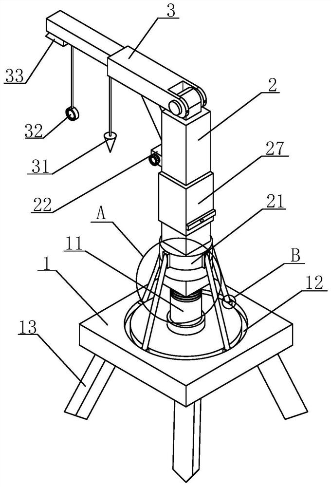
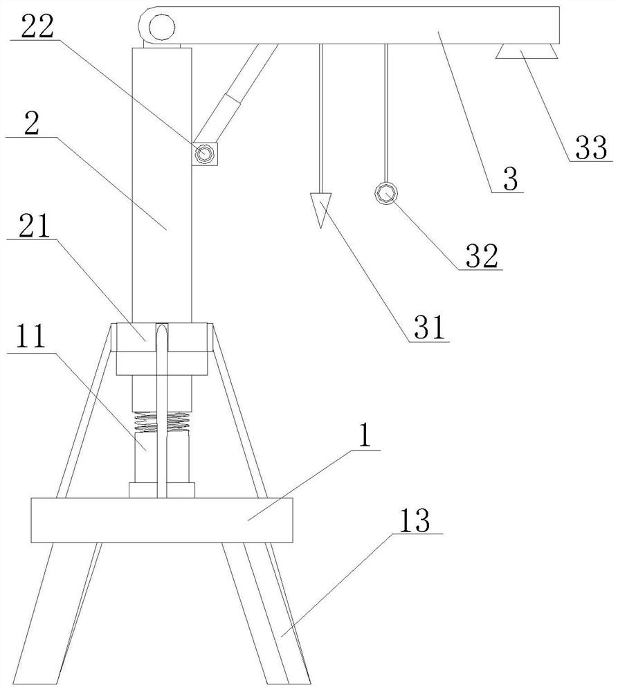
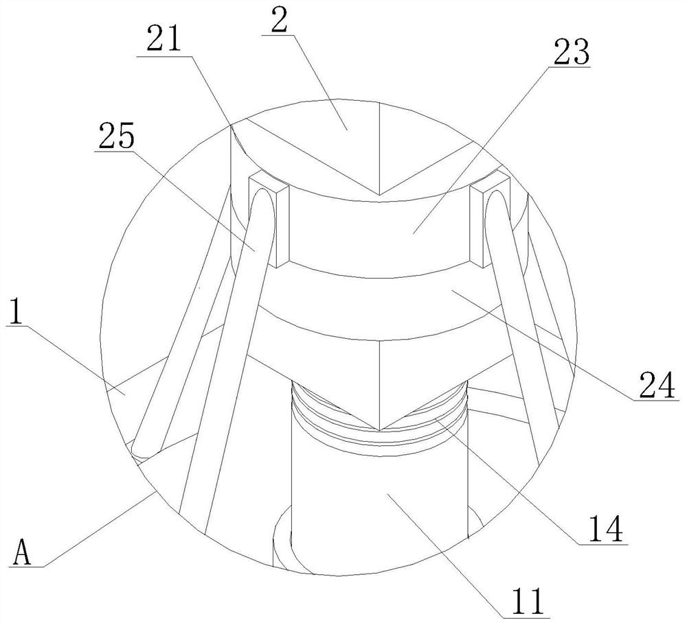
[0024] Example 1, in the present embodiment, the base 1 includes a connecting column 11, the outer wall of the connecting column 11 is provided with a slow pressure thread 14, the connection column 11 is connected by a bottom inner wall thread of the column 2 is provided with a slow pressure thread 14, the surface of the base 1 and away from the circumference of the connecting column 11 is opened with a buffer groove 12, the bottom four corners of the base 1 are fixed to connect the support legs 13, wherein the cushion groove 12 is provided to facilitate the rotation of the block 26 in the buffer groove 12 rotation, Convenient column 2 supports when turning to adjust the height.

Embodiment 2

[0025] Example 2, the outer wall of the column 2 and near the bottom is provided with a support base 21, the outer wall of the column 2 and near the top is provided with a hydraulic mechanism 22, preferably, the hydraulic mechanism 22 is set to adjust the angle of the telescopic monitoring rod 3, so that the prism is located in the field of view of the total station, the height of the prism is determined by the total station, and then the height difference is detected by other detection points, the support base 21 includes a pressure rotating seat 23 and a pressure extrusion seat 24, The bottom inner wall of the pressure extrusion seat 24 is connected to the inner wall rotation of the rotating seat 23, preferably, the rotating block 23 is set to facilitate the rotation of the guard rod 25, the outer wall of the rotating seat 23 is evenly provided with a guard rod 25, the bottom of the guard rod 25 is fixedly connected with the slider 26, the outer wall of the slider 26 is connecte...

Embodiment 3

[0026] Example 3, in the present embodiment, the top center of the column 2 is provided with a rotating block, the outer wall of the rotating block is provided with a through hole, the telescopic monitoring rod 3 near the end of the column 2 is opened with a rotating groove, the inner wall of the rotating groove is opened with a through hole that is compatible with the rotating block, and the two adaptable through holes the inner wall is inserted with a fixed pin, the telescopic monitoring rod 3 is fixed by the fixed pin set with the column 2 fixed connection, the top of the hydraulic mechanism 22 is provided with a hydraulic rod, The top of the hydraulic rod is fixedly connected to the bottom of the telescopic monitoring rod 3 and away from the side of the lead hammer 31.

[0027] The following is a specific introduction to the working principle of the automatic deformation monitoring equipment for the subway foundation pit.

[0028] as Figure 1-4 As shown, when used, first set the...


PUM


Abstract

The invention discloses an automatic deformation monitoring equipment for a subway foundation pit, which relates to the technical field of foundation pit construction monitoring, and comprises a base, the base is arranged horizontally, and a column is fixedly connected to the center of the top of the base, and the column is a vertical column. The top of the column is movable and a telescopic monitoring rod is arranged horizontally. The telescopic monitoring rod includes a plumb weight. On the monitoring rod, a monitoring mechanism is provided at the bottom of the other end of the telescopic monitoring rod away from the column. When the device works before each measurement in the present invention, the self-position coordinates of the device are first corrected through the monitoring point, and the hydraulic mechanism set up works to adjust the angle of the telescopic monitoring rod to determine the uplift height of the foundation pit. The deformation data of all detection points at the bottom of the pit are recorded and measured, and then monitored by the detection mechanism.

Description

Technical field [0001] The present invention relates to the field of excavation construction monitoring technology, specifically to a subway excavation automated deformation monitoring equipment. Background [0002] Urban subway is a hot spot for infrastructure investment in China in recent years, and vigorously developing urban subway has become the focus of municipal construction in large and medium-sized cities. Most of China's subways are buried more than ten or twenty meters deep underground, or even deeper, and it is indispensable to ensure the safety of construction. Statistical analysis found that any one foundation pit accident was invariably associated with poor monitoring or inaccurate forecasting of dangerous situations. Therefore, the safety and stability of the foundation pit determines whether the entire project construction can be successfully completed, and the displacement monitoring related to the foundation pit occupies a very important position in the constru...

Claims


Application Information

Patent Timeline
Patent Type & Authority Patents(China)
IPC IPC(8): E02D33/00E02D17/02G01B21/32G01C15/00G01C5/00
CPCE02D33/00E02D17/02G01B21/32G01C15/00G01C5/00
Inventor 柏文锋农兴中张华刘成军闵星邓显威彭丕洪郝传才吴增伟
Owner GUANGZHOU METRO DESIGN & RES INST
Learn More