Residual current monitoring system and monitoring method for low-voltage alternating current power supply system
What is AI technical title?
AI technical title is built by Patsnap AI team. It summarizes the technical point description of the patent document.
A technology of residual current and AC power supply, which is applied in the field of residual current monitoring system of low-voltage AC power supply system, and can solve the problems of affecting the sampling of current transformers and inaccurate monitoring results.
Pending Publication Date: 2021-07-06
STATE GRID CORP OF CHINA +1
View PDF5 Cites 2 Cited by
Summary
Abstract
Description
Claims
Application Information
AI Technical Summary
This helps you quickly interpret patents by identifying the three key elements:
Problems solved by technology
Method used
Benefits of technology
Problems solved by technology
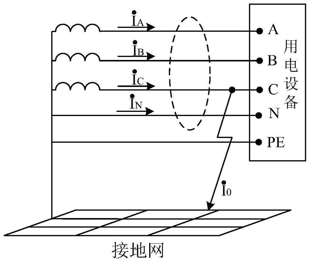
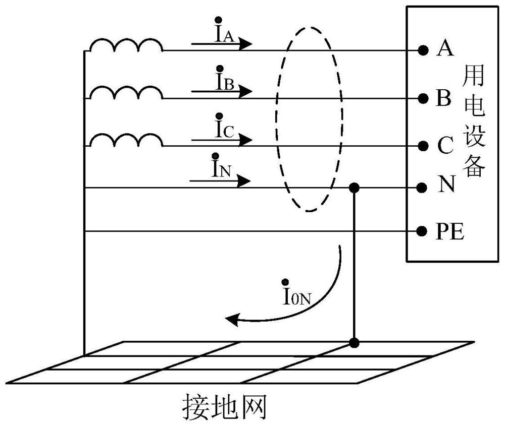
[0009] The grounding mode of the low-voltage AC power supply system in power plants and substations is the TN system. If the residual current of the low-voltage AC power supply system for the station is monitored, the neutral line from the monitoring point to the end of the loop should not be repeatedly grounded, otherwise the grounding network will be affected by shunting. Current transformer sampling, resulting in inaccurate monitoring results, such as figure 2 shown
Method used
Image
Click on the blue label to locate the original text in one second.
Reading with bidirectional positioning of images and text.
[0074] For the 380V feeder panel, each feeder circuit is tested by ABC and N passing through two transformers respectively, and Bodian S10 debugging device is used to add:
[0075] 1) (10mA∠0°, 10mA∠0°), (1A∠0°, 1A∠0°) current, the display value of the vector calculation composite value of the residual current monitoring and protection device is 15mA and 1.997A respectively;
[0076] 2) (10mA∠0°, 10mA∠180°), (100mA∠0°, 100mA∠180°) current, and the display value of the vector calculation composite value of the residual current monitoring and protection device is 0mA and 0mA respectively;
[0077] 3) (100mA∠0°, 100mA∠120°), (1A∠0°, 1A∠120°) currents, and the display values of the residual current monitoring and protection device vector calculation composite values are 169mA and 1.726A respectively.
Embodiment 2
[0079] Installation of residual current monitoring at the neutral point grounding of substation transformers
[0080] In a 500 kV substation, a set of residual current transformers are respectively installed at the grounding down conductors of the neutral point of the substation transformers for 3 substations.
[0081] On-site test The currents of substations #0, #1, and #2 are 3.234A, 7.190A, and 9.444A respectively, and the combined residual current is 0.251A.
Embodiment 3
[0083] Perform residual current monitoring on the dual power supply circuit of power box 1 of 500kV power distribution device. The current value of "power box 1 (one) of 500kV power distribution device" is 3.552A, and the current value of "power box 1 (two) of 500kV power distribution device" is 3.560A, the actual residual current value of the dual power circuit after synthesis is 0.075A.
PUM
Abstract
The invention discloses a residual current monitoring system and a monitoring method for a low-voltagealternating current power supply system, which can solve the problems of neutral lineshunting caused by parallel connection of neutral lines on load sides of dual power supplies or looped network loops in a power plant and a transformer substation, inconvenience in mounting a residual current transformer by a bus arrangement structure in a central distribution panel and the like. Insulation states of the low-voltage alternating-current power supply system of the power plant and the transformer substation are monitored in real time, abnormal insulation conditions of loops of the low-voltage alternating-current power supply system are found in time, a fireproof capability of the low-voltage alternating-current power supply system of the power plant and the transformer substation is improved, and safe and reliable operation of a power grid is ensured.
Description
technical field [0001] The invention relates to a residual current monitoring system and a monitoring method of a low-voltage AC power supply system. Background technique [0002] At present, the low-voltage AC power supply systems used in power plants and substations are not equipped with insulation monitoring devices, and hidden problems such as insulation degradation of low-voltage AC cables cannot be detected in time. Failure of low-voltage AC cable insulation may cause fire accidents such as equipment and cable trenches in the station, which in turn affects The main equipment runs safely and stably. Residual current monitoring is one of the most effective measures to solve the early warning of insulation faults in low-voltage power distribution systems and prevent personal electric shocks and electrical fires. [0003] The traditional residual current monitoring of low-voltage AC powerdistribution system is based on Kirchhoff's current law, such as figure 1 shown. ...
Claims
Application Information
Patent Timeline
Application Date:The date an application was filed.
Publication Date:The date a patent or application was officially published.
First Publication Date:The earliest publication date of a patent with the same application number.
Issue Date:Publication date of the patent grant document.
PCT Entry Date:The Entry date of PCT National Phase.
Estimated Expiry Date:The statutory expiry date of a patent right according to the Patent Law, and it is the longest term of protection that the patent right can achieve without the termination of the patent right due to other reasons(Term extension factor has been taken into account ).
Invalid Date:Actual expiry date is based on effective date or publication date of legal transaction data of invalid patent.

