
Parameter design method for electric field coupled wireless power transmission system with constant current output

A technology of wireless power transmission and electric field coupling, applied in electrical digital data processing, computer-aided design, calculation, etc., can solve problems such as unfavorable guiding circuit parameter design, unfavorable engineering realization, unclear resonance relationship, etc.

Active Publication Date: 2021-07-06
NAVAL UNIV OF ENG PLA
View PDF6 Cites 0 Cited by
  • Summary
  • Abstract
  • Description
  • Claims
  • Application Information

AI Technical Summary

Problems solved by technology

At present, the constant current output method of double-sided LC compensation electric field coupling wireless power transmission is mainly realized by setting the working frequency and the natural resonant frequency of the LC compensation network at the transmitting end or receiving end to meet a specific relationship. The main disadvantage is that the compensation The resonance relationship between the various components and coupling capacitors in the network is not clear, which is not conducive to guiding the design of circuit parameters, and the operating frequency set by the condition of constant current output is very close to the natural resonance frequency of the LC compensation network under certain circumstances , is not conducive to engineering realization

Method used


Image

  • Parameter design method for electric field coupled wireless power transmission system with constant current output
  • Parameter design method for electric field coupled wireless power transmission system with constant current output
  • Parameter design method for electric field coupled wireless power transmission system with constant current output

Examples


Embodiment Construction

[0030] The technical solutions in the embodiments of the present application will be clearly and completely described below in conjunction with the drawings in the embodiments of the present application.

[0031] The terms "first", "second", "third" and the like in the description and claims of the present application and the above drawings are used to distinguish different objects, rather than to describe a specific order. Furthermore, the terms "include" and "have", as well as any variations thereof, are intended to cover a non-exclusive inclusion. For example, a process, method, system, product or device comprising a series of steps or units is not limited to the listed steps or units, but optionally also includes unlisted steps or units, or optionally further includes For other steps or units inherent in these processes, methods, products or devices.

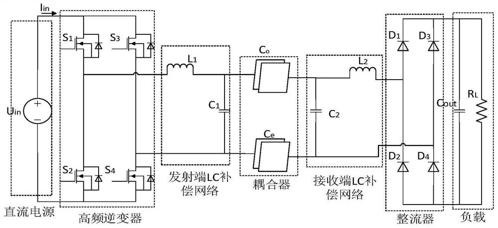
[0032] figure 1 A schematic diagram of the circuit structure of the electric field coupling wireless power transfer syst...


PUM


Abstract

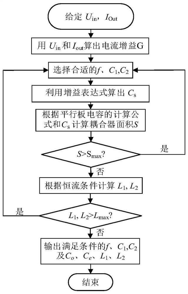
The invention discloses a parameter design method for an electric field coupled wireless power transmission system with constant current output, and the method comprises the steps: deducing a constant output current condition and a current gain expression during constant current output on the basis of analyzing the total input impedance of the electric field coupled wireless power transmission system; determining the working frequency and compensation capacitance of the system according to the current gain expression and by taking the area of the coupler as a constraint condition; calculating compensation inductance according to the constant condition of the output current, the determined working frequency and the compensation capacitance; if any one of the compensation inductors is greater than a preset inductance threshold value, modifying at least one of the working frequency and the compensation capacitor until the compensation inductors are not greater than the inductance threshold value; and performing a simulation experiment on system parameters designed based on the method, and showing that system output current is irrelevant to load impedance. According to the design method, the problem that the output current is unstable when the system load impedance changes is solved, and the system has the excellent output current constant characteristic.

Description

technical field [0001] The present application relates to the technical field of wireless power transmission, and more specifically, to a parameter design method of an electric field coupling wireless power transmission system with constant current output. Background technique [0002] Electric field coupled wireless power transfer is a near-field wireless power transfer method. It has been confirmed by many experts and scholars at home and abroad that it can efficiently transfer power at different power levels and has its unique advantages. [0003] The constant output characteristic is a very important aspect to ensure the quality of power supply, and the current research focus is also devoted to making the wireless power transfer system provide stable output. Some electrical equipment expects a constant current as an input, for example, most batteries require a stable current in the early stage of charging. At present, the constant current output method of electric field...

Claims


Application Information

Patent Timeline
Patent Type & Authority Applications(China)
IPC IPC(8): H02J50/05H02J50/40G06F30/367
CPCH02J50/05H02J50/40G06F30/367
Inventor 熊乔邵英吴旭升孙盼孙军蔡进王蕾
Owner NAVAL UNIV OF ENG PLA
Learn More