Shrub plant pruning device applied to landscaping management
A landscaping and pruning device technology, applied in the field of landscaping management, can solve the problems of clumsy use, hidden safety hazards, leakage, etc., and achieve the effect of enhancing the convenience of use and improving safety
- Summary
- Abstract
- Description
- Claims
- Application Information
AI Technical Summary
Problems solved by technology
Method used
Image

Examples
Embodiment Construction
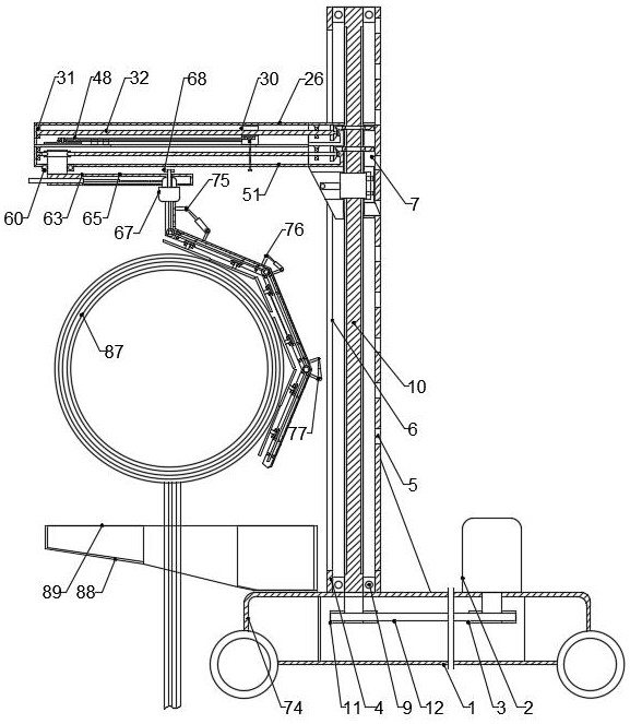
[0030] The present invention is specifically described below in conjunction with accompanying drawing, as Figure 1-13 As shown, a shrub pruning device applied to landscaping management includes a rectangular base 1, the upper surface of the rectangular base 1 is provided with a linkage lifting mechanism, one end of the linkage lifting mechanism is provided with a hidden cross-cutting mechanism, and the lower end of the hidden cross-cutting mechanism is Equipped with adjustable trimming mechanism;
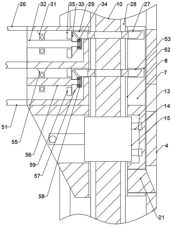
[0031]The linkage lifting mechanism includes a rotating motor 2 on one end of the upper surface of the rectangular base 1, the rotating end of the rotating motor 2 extends into the rectangular base 1, a belt pulley 3 is installed on the rotating end of the rotating motor 2, and a rectangular support tube 4 is installed on the other end of the upper surface of the rectangular base 1 , the side surface of the rectangular support tube 4 is provided with a rectangular through hole 5, t...
PUM
 Abstract
Description
Claims
Application Information