Auxiliary filling device and brake fluid filling system

A filling device and filling system technology, which is applied in the field of auxiliary filling devices and brake fluid filling systems, can solve the problems of low exhaust operation efficiency and unclean exhaust, etc.

Active Publication Date: 2022-05-20
ANHUI JIANGHUAI AUTOMOBILE GRP CORP LTD
View PDF7 Cites 0 Cited by
  • Summary
  • Abstract
  • Description
  • Claims
  • Application Information

AI Technical Summary

Problems solved by technology

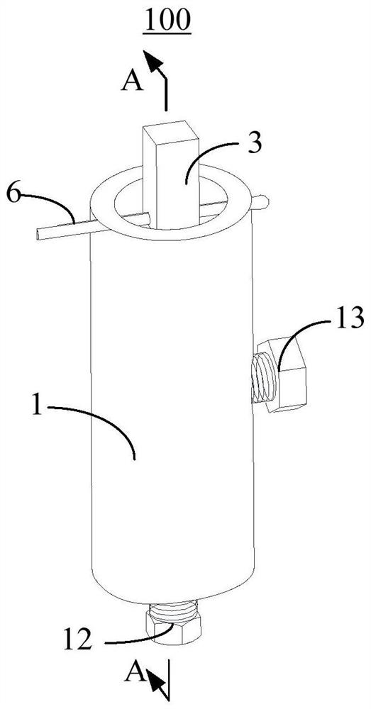
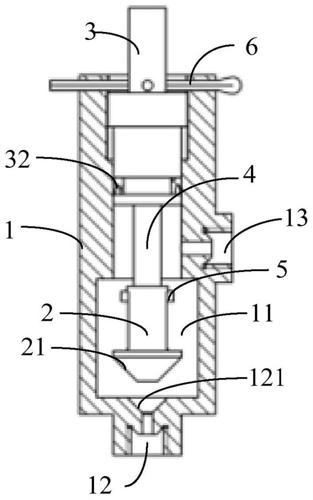
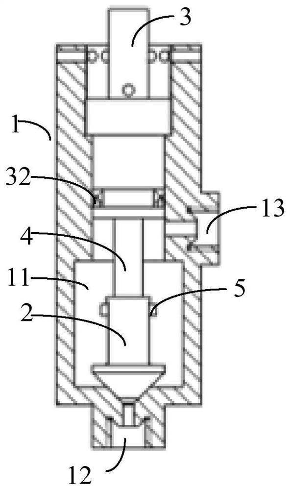
[0003] The main purpose of the present invention is to propose an auxiliary filling device and a brake fluid filling system, aiming to solve the problem of low efficiency in filling brake fluid and exhausting the clutch hydraulic pipeline, and the problem of dirty exhaust

Method used


Image

  • Auxiliary filling device and brake fluid filling system
  • Auxiliary filling device and brake fluid filling system
  • Auxiliary filling device and brake fluid filling system

Examples


Embodiment Construction

[0049] The following will clearly and completely describe the technical solutions in the embodiments of the present invention with reference to the accompanying drawings in the embodiments of the present invention. Obviously, the described embodiments are only part of the embodiments of the present invention, not all of them. Based on the embodiments of the present invention, all other embodiments obtained by persons of ordinary skill in the art without creative efforts fall within the protection scope of the present invention.

[0050] It should be noted that if there are directional indications involved in the embodiment of the present invention, the directional indications are only used to explain the relative positional relationship, movement conditions, etc. between the components in a specific posture. If the specific posture changes , then the directional indication changes accordingly.

[0051] In addition, if there are descriptions involving "first", "second" and so o...


PUM


Abstract

The present invention provides an auxiliary filling device and a brake fluid filling system, wherein the auxiliary filling device is used on a hydraulic clutch pedal operating mechanism, the hydraulic clutch pedal operating mechanism includes a clutch master cylinder, and the auxiliary filling The injection device includes a housing and a filling piston. The housing is placed vertically. The housing is provided with a cavity. The bottom wall of the cavity is provided with a pipeline inlet. The pipeline inlet is used for communication. It is arranged at the oil outlet of the clutch master cylinder; the filling piston can be movable up and down and installed on the upper end of the cavity, and the filling piston has a seal that seals the pipeline inlet on its movable stroke position and open the communication position of the pipeline inlet. In the technical solution of the present invention, the auxiliary filling device is used to increase the vacuum degree in the clutch master cylinder to improve the filling and exhaust efficiency of the clutch master cylinder.

Description

technical field [0001] The invention relates to the technical field of hydraulic clutches, in particular to an auxiliary filling device and a brake fluid filling system. Background technique [0002] In the factory, when the automobile is produced and debugged, the vacuum filling equipment is generally used to fill the clutch hydraulic line with brake fluid and exhaust it at the same time, so the work efficiency is high. However, the vacuum filling equipment is bulky and expensive, and few ordinary auto repair shops are equipped with vacuum filling equipment. In the absence of vacuum filling equipment, the method of stepping on the clutch pedal must be used to fill the clutch hydraulic line with brake fluid and exhaust. The operation efficiency is low, labor and time-consuming, and the exhaust is often dirty. Contents of the invention [0003] The main purpose of the present invention is to provide an auxiliary filling device and a brake fluid filling system, aiming at so...

Claims


Application Information

Patent Timeline
Patent Type & Authority Patents(China)
IPC IPC(8): B67D7/04B67D7/06B67D7/38B67D7/62B67D7/78F16D25/12
CPCF16D25/12B67D7/04B67D7/06B67D7/38B67D7/62B67D7/78
Inventor 郭静宋康杨允辉余纪邦葛士显
Owner ANHUI JIANGHUAI AUTOMOBILE GRP CORP LTD
Why Eureka
Try Eureka