
Worm cross-rod distance detection device with automatic deviation correction function and worm cross-rod distance detection method

An automatic deviation correction and detection device technology, which is applied in the direction of mechanical clearance measurement, etc., can solve the problems of lack of deviation correction function, influence on detection accuracy, wear and other problems, and achieve the effect of improving detection accuracy and service life, ensuring detection accuracy, and compact overall structure

Active Publication Date: 2021-07-09
NINGBO XIASHA GEARS
View PDF9 Cites 0 Cited by
  • Summary
  • Abstract
  • Description
  • Claims
  • Application Information

AI Technical Summary

Problems solved by technology

[0004] In the prior art, there is still a lack of a better detection device for the span of the worm, which takes a long time to detect and the detection efficiency is low
Moreover, some current detection devices lack the deviation correction function, which will cause the inclination angle of the detection head to be inconsistent with that of the upper ring gear of the worm, so that when the detection head is inserted into the gap of the ring gear, it cannot be perfectly matched and inserted, and the insertion depth is inaccurate, resulting in detection Accuracy drops
In the prior art, there are also some technologies in which the detection head can be rotated at a certain angle for insertion detection, but the structural matching is poor, the friction is large, and the wear is serious after long-term use, which also affects the detection accuracy.

Method used


Image

  • Worm cross-rod distance detection device with automatic deviation correction function and worm cross-rod distance detection method
  • Worm cross-rod distance detection device with automatic deviation correction function and worm cross-rod distance detection method
  • Worm cross-rod distance detection device with automatic deviation correction function and worm cross-rod distance detection method

Examples


Embodiment Construction

[0042] The present invention will be further described in detail below in conjunction with the accompanying drawings and specific embodiments.

[0043] In the following embodiments, the same or similar symbols throughout represent the same or similar components or components with the same or similar functions, and the following embodiments described with reference to the accompanying drawings are exemplary and are only used to explain the present invention, rather than understanding To limit the present invention.

[0044] In the description of the present invention, it should be understood that the terms: center, longitudinal, transverse, length, width, thickness, up, down, front, back, left, right, vertical, horizontal, top, bottom, inside, outside, Clockwise, counterclockwise, etc. indicate the orientation or positional relationship based on the orientation or positional relationship shown in the drawings, and are only for the convenience of describing the present invention...


PUM


Abstract

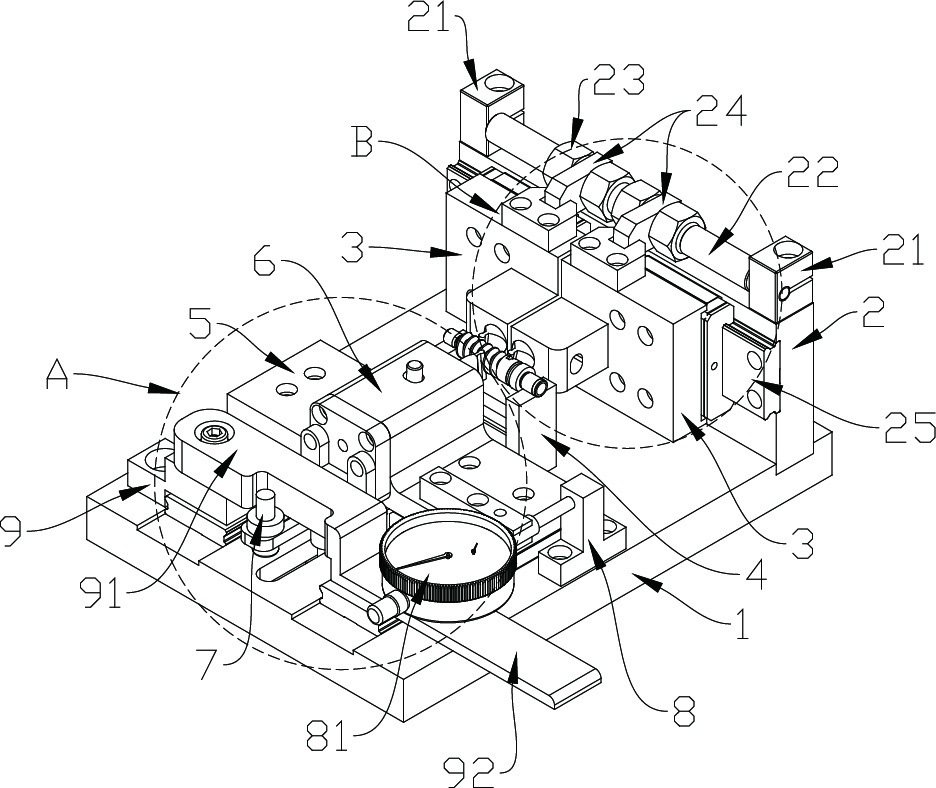
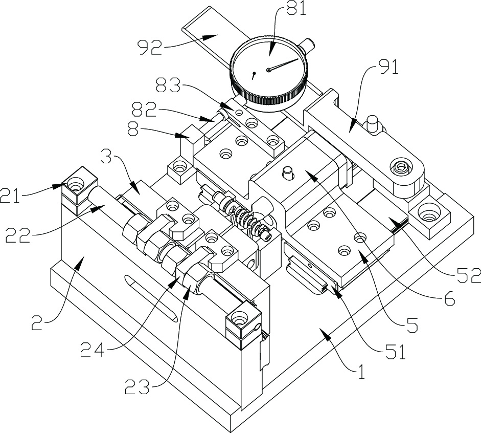
A worm cross-rod distance detection device with an automatic deviation correction function comprises a base, and the base is provided with a first positioning assembly, a second positioning assembly and a measuring assembly. A worm placing assembly is arranged between the first positioning assembly and the second positioning assembly; the first positioning assembly comprises a side plate arranged on the base, two movable first positioning seats are arranged at one side of the side plate, a first positioning column is arranged on each first positioning seat and can axially rotate, and a first positioning head is arranged at the end of each first positioning column. According to the worm cross-rod distance detection device and method with the automatic deviation correction function, the device is compact in overall structure and reasonable in design, the worm is positioned through the three detection heads, the positioning precision is high, the detection heads have the automatic rotation deviation correction function, operation is convenient, and the detection precision is high.

Description

technical field [0001] The invention belongs to the field of worm screw measuring equipment, and in particular relates to a worm screw cross-rod distance detection device and method with an automatic deviation correction function. Background technique [0002] The worm is a kind of hardware that is widely used. It generally works with the worm gear. The worm gear structure is often used to transmit the motion and power between two interlaced shafts. The worm gear and the worm are equivalent to the gear and the rack in the middle plane. Similar to screw shape. [0003] For worms used in precision occasions, whether the size and depth of the ring gear on the surface are in compliance has a great impact on the product quality of the worm. Therefore, before the finished worm leaves the factory, it is necessary to test the ring gear on the surface. Detect the depth of the ring gear, detect the gap between the ring gear, detect the inclination of the ring gear, and detect the dis...

Claims


Application Information

Patent Timeline
IPC IPC(8): G01B5/14
CPCG01B5/14
Inventor 郑卫敏
Owner NINGBO XIASHA GEARS
Learn More