Optical fiber box

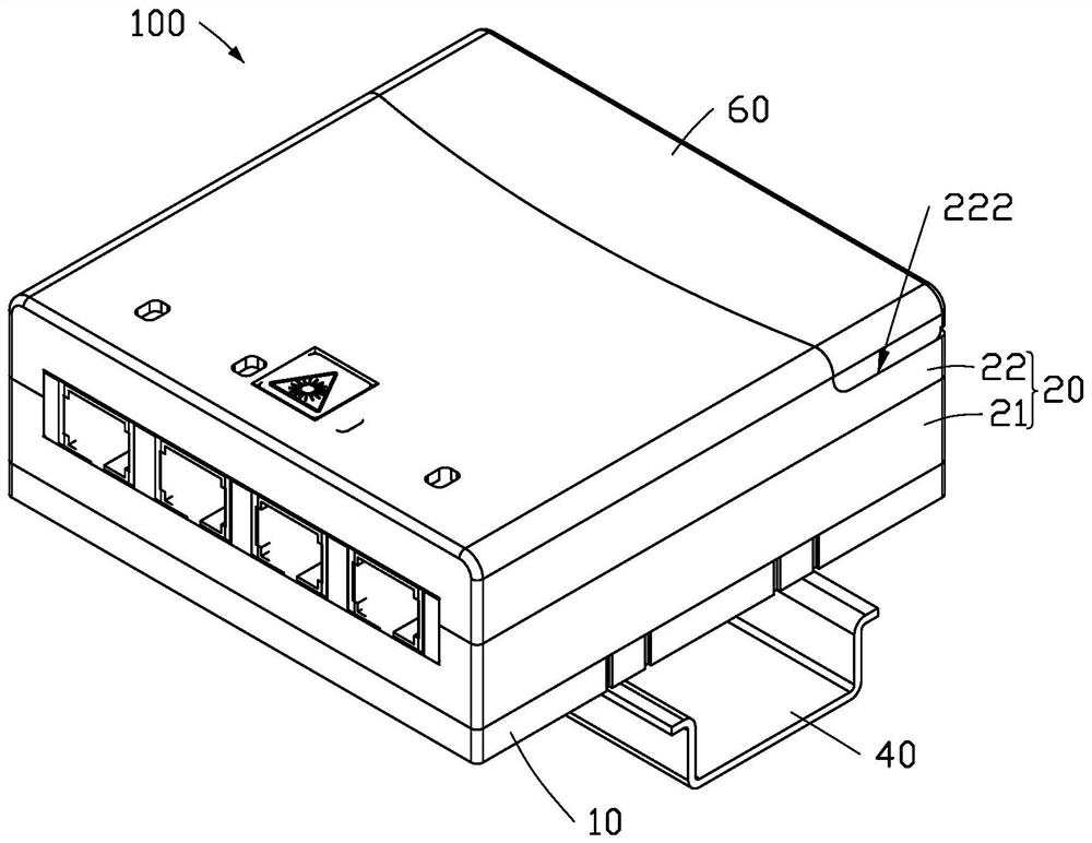
A fiber optic box and optical fiber technology, which is applied in the field of fiber optic boxes, can solve the problems of fixed installation position, difficulty in adjustment, and the inability to adjust the number of wire holes according to the actual situation, so as to achieve the effect of improving applicability and flexible and adjustable installation position

Pending Publication Date: 2021-07-09
ZHONGTIAN BROADBAND TECH
View PDF8 Cites 0 Cited by
  • Summary
  • Abstract
  • Description
  • Claims
  • Application Information

AI Technical Summary

Problems solved by technology

[0003] The traditional optical fiber panel box is only suitable for matching with the cassette embedded in the wall, or it is only suitable for being directly installed on the wall. The installation position is relatively fixed and

Method used


Image

  • Optical fiber box
  • Optical fiber box
  • Optical fiber box

Examples


Embodiment Construction

[0028] The following will clearly and completely describe the technical solutions in the embodiments of the application with reference to the drawings in the embodiments of the application. Apparently, the described embodiments are only some, not all, embodiments of the application.

[0029] It should be noted that when an element is referred to as being “fixed” to another element, it can be directly on the other element or there can also be an intervening element. When an element is referred to as being "connected to" another element, it can be directly connected to the other element or intervening elements may also be present. When an element is referred to as being "disposed on" another element, it can be directly on the other element or intervening elements may also be present. The terms "vertical," "horizontal," "left," "right," and similar expressions are used herein for purposes of illustration only.

[0030] Unless otherwise defined, all technical and scientific terms...


PUM


Abstract

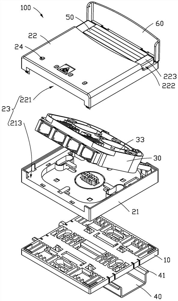
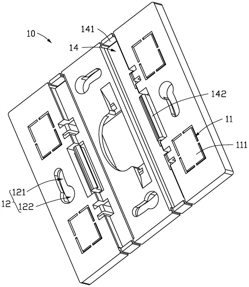
The invention provides an optical fiber box. The optical fiber box comprises a shell, an accommodating disc and a mounting plate. The shell comprises a first shell and a second shell. And the accommodating disc is arranged between the first shell and the second shell and is used for connecting and storing optical fibers. And the mounting plate is detachably connected with the first shell, so that the optical fiber box can be matched with a cassette in a wall body for use and can also be directly mounted on the wall body, and the use environment is diversified. A plurality of wire inlets are formed in the mounting plate at intervals, through holes communicated with the wire inlets are formed in the side, facing the mounting plate, of the first shell, and detachable blocking pieces are arranged in the wire inlets. The use number of the wire inlets can be adjusted according to the actual condition, the universality and applicability of the optical fiber box are improved, and the construction and maintenance difficulty is reduced. And the mounting plate is also provided with a plurality of mounting holes for positioning the mounting plate, and the plurality of mounting holes are distributed in a square array, so that the mounting position of the optical fiber box is flexible and adjustable.

Description

technical field [0001] The present application relates to the technical field of optical fiber equipment, in particular to an optical fiber box. Background technique [0002] With the large-scale construction of FTTH, the network is deeply affecting our lives. The deployment of optical fiber networks and the deployment of indoor optical cables are extremely important links. Optical fiber panel boxes have become important equipment for fiber-to-the-home and fiber-to-the-desktop . [0003] The traditional optical fiber panel box is only suitable for matching with the cassette embedded in the wall, or it is only suitable for being directly installed on the wall. The installation position is relatively fixed and difficult to adjust. The number of wire holes on the box body cannot be adjusted according to the actual situation, the applicability of the optical cable is not fully considered, and the construction and maintenance are inconvenient. Contents of the invention [000...

Claims


Application Information

Patent Timeline
IPC IPC(8): G02B6/44
CPCG02B6/4446
Inventor 缪冬青蒲维孙建华吴媛媛赵玉立蒋志祥
Owner ZHONGTIAN BROADBAND TECH
Why Eureka
Try Eureka