Hydraulic drive reciprocating duplex pump

A double-cylinder pump and reciprocating technology, which is applied in the direction of liquid displacement machinery, pumps, piston pumps, etc., can solve the problems of complex oil circuit connection, large overall volume, and unusability, so as to ensure synchronous linkage and overall volume Smaller and easier to disassemble and maintain

Active Publication Date: 2014-05-28
东营盛昶石油机械有限公司
View PDF5 Cites 8 Cited by
  • Summary
  • Abstract
  • Description
  • Claims
  • Application Information

AI Technical Summary

Problems solved by technology

This kind of mud pump generally has the following problems: 1. It adopts the crankshaft connecting rod and gear transmission structure, the overall volume is too large, and it is inconvenient to disassemble and maintain; The gear is then transmitted to the crankshaft, resulting in large losses. The crankshaft rotates to push the piston or plunger, and the force needs to be decomposed and the uniformity of its operation cannot be guaranteed. The speed regulation can only be carried out in the stop state, which is inconvenient to use
Due to the different resistance of the pump head in the process of water absorption and drainage, in order to ensure the synchronization between the hydraulic cylinders, a high-pressure pump and a low-pressure pump must be used together through several solenoid valves. The oil circuit connection is more complicated and the cost is high. In the field It is even more unusable when there is no electricity at work

Method used


Image

  • Hydraulic drive reciprocating duplex pump
  • Hydraulic drive reciprocating duplex pump

Examples


Embodiment Construction

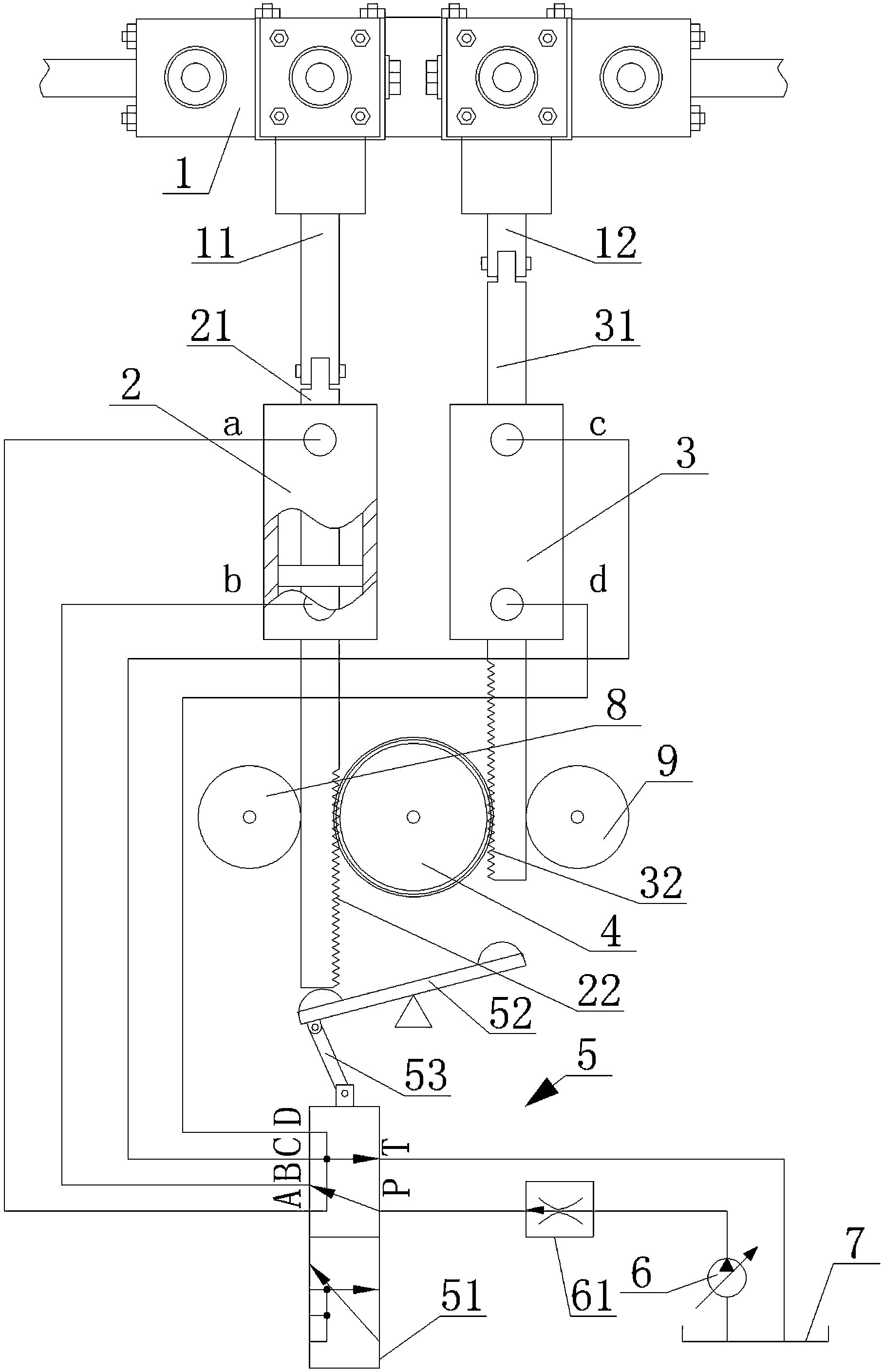
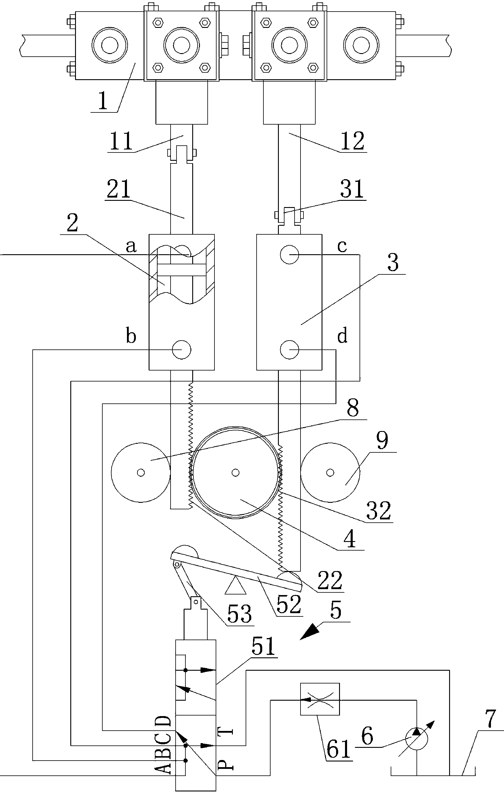
[0015] From figure 1 and figure 2 It can be seen that the hydraulically driven reciprocating double-cylinder pump of the present invention includes a double-cylinder pump head 1 installed on the frame, a single-piston double-rod hydraulic cylinder one 2, a single-piston double-rod hydraulic cylinder two 3 , gear 4, reversing device 5, oil pump 6 and oil tank 7, double-cylinder pump head 1 includes piston rod one 11 and piston rod two 12 respectively connected with each cylinder to drive suction and discharge movement, reversing device 5 includes two-position six-way switch Directional valve 51, transmission lever 52 and connecting rod 53, single-piston double-rod hydraulic cylinder one 2 and single-piston double-rod hydraulic cylinder two 3 are arranged in parallel on the frame, single-piston double-rod hydraulic cylinder one 2 One end of the piston rod three 21 is linearly connected with the piston rod one 11 to push it to reciprocate in the pump cylinder, and one end of th...


PUM


Abstract

The invention discloses a hydraulic drive reciprocating duplex pump. The hydraulic drive reciprocating duplex pump comprises a duplex pump head installed on a rack. Cylinders of the duplex pump head are driven by a first piston rod and a second piston rod to make suction and discharging motion respectively. The duplex pump further comprises gears, a reversing device, an oil pump, an oil tank, a first single-piston-type double-outlet-rod hydraulic cylinder and a second single-piston-type double-outlet-rod hydraulic cylinder, wherein the first single-piston-type double-outlet-rod hydraulic cylinder and the second single-piston-type double-outlet-rod hydraulic cylinder are arranged on the rack in parallel. The reversing device comprises a two-position six-way reversing valve and a transmission lever, one ends of the piston rods of both the hydraulic cylinders are linearly connected with the corresponding piston rods of the duplex pump head respectively to push the piston rods to make reciprocating motion in the pump cylinders, corresponding tooth patterns are formed in the opposite faces of the other ends of the piston rods of the hydraulic cylinders, and the gears are arranged between the piston rods of the hydraulic cylinders at the end and meshed with the tooth patterns on all the sides to drive the piston rods to move reversely. The hydraulic drive reciprocating duplex pump is small in overall size and convenient to detach and maintain, force does not need to be decomposed or worn down, the overall stroke is performed at a more constant speed, stepless speed regulation can be carried out without shutdown, the synchronous co-movement is strong, and the suction and the discharging are more stable.

Description

technical field [0001] The invention belongs to the field of mud pumps, in particular to a hydraulically driven reciprocating double-cylinder pump. Background technique [0002] Mud pump refers to the machinery that transports flushing fluid such as mud or water into the borehole during the drilling process. It is an important part of drilling equipment. In the commonly used positive circulation drilling, it is to send the surface flushing medium-clean water, mud or polymer flushing fluid directly to the bottom of the drill bit through a high-pressure hose, faucet and the center hole of the drill string under a certain pressure to achieve The purpose of cooling the drill bit, removing the cutting cuttings and transporting them to the surface. [0003] Commonly used mud pumps are piston or plunger type. The crankshaft of the pump is driven by the power machine to rotate. The crankshaft drives the piston or plunger to reciprocate in the pump cylinder through the crosshead. Un...

Claims


Application Information

Patent Timeline
Patent Type & Authority Applications(China)
IPC IPC(8): F04B23/06F04B9/10
Inventor 龙科
Owner 东营盛昶石油机械有限公司
Why Eureka
Try Eureka