Manufacturing method of copper/steel combination injection mold with honeycomb and planted nail interface structure

An injection mold and interface structure technology, applied in the field of mold manufacturing, can solve the problems of interface residual stress cracking, excessive bonding interface, complex distribution, etc., achieve low-cost rapid manufacturing, less machining, and increase the effect of bonding area

Active Publication Date: 2020-09-29
NANJING ENIGMA IND AUTOMATION TECH CO LTD
View PDF14 Cites 2 Cited by
  • Summary
  • Abstract
  • Description
  • Claims
  • Application Information

AI Technical Summary

Problems solved by technology

However, there is a bottleneck problem in the current copper / steel composite injection mold manufacturing: it is difficult to form a high-quality bond between copper and steel
There are three main reasons why it is difficult to combine copper and steel with high quality in copper / steel composite injection molds: (1) There are great differences in physical and chemical properties between copper and steel, which makes it difficult to form a high-quality copper / steel connection interface. The strength is combined and the connection interface produces a large residual stress; (2) The interface between copper and steel in the copper / steel composite injection mold is too large, resulting in a larger residual stress and a more complex distribution of the connection interface; (3) Copper / steel If the joint interface profile of copper and steel in the composite injection mold remains similar to the cavity surface, it is also a complex space surface shape, which will lead to the interface residual stress is more likely to cause local cracking, and it will also cause great difficulties to the connection process
Copper / steel adopts planar combination, which can greatly reduce the difficulty of combining copper and steel in the copper / steel composite injection mold, but the thickness of the steel reinforcement layer corresponding to the planar combination is very uneven, which is not conducive to the rapidity and uniformity of heat conduction

Method used


Image

  • Manufacturing method of copper/steel combination injection mold with honeycomb and planted nail interface structure
  • Manufacturing method of copper/steel combination injection mold with honeycomb and planted nail interface structure
  • Manufacturing method of copper/steel combination injection mold with honeycomb and planted nail interface structure

Examples


Embodiment Construction

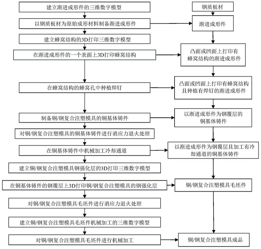
[0042] The present invention will be further described below in conjunction with accompanying drawing.

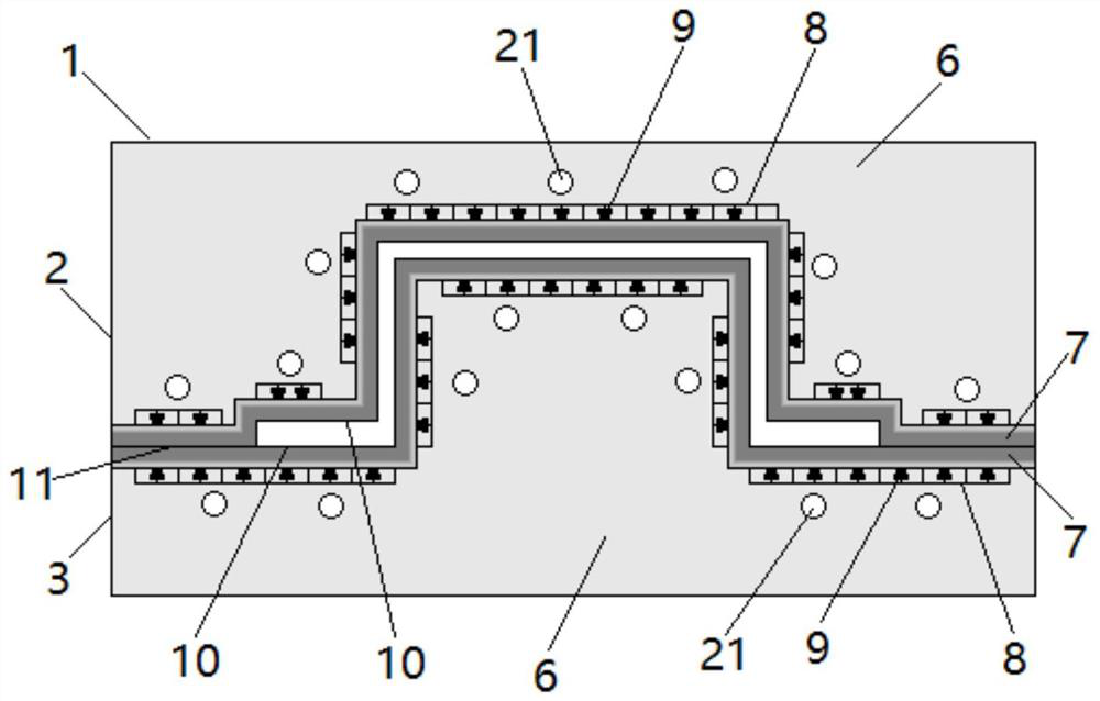
[0043] The present invention adopts the copper / steel compound injection mold manufacturing method of honeycomb plus planting nail interface structure, and manufacturing process is as follows figure 1 As shown, it solves the bottleneck problem that copper and steel are difficult to form a high-quality combination in the copper / steel composite injection mold, and at the same time makes the copper / steel bonding interface profile and the cavity surface of the copper / steel composite injection mold with a honeycomb plus nail structure Similarly, the copper / steel interface that realizes the honeycomb nailing structure is combined with high quality in the form of a spatially complex surface.

[0044] The honeycomb structure is the best topological structure covering a two-dimensional plane. It is a structure composed of regular hexagonal honeycomb holes arranged symmetrically back ...


PUM

PropertyMeasurementUnit
diameteraaaaaaaaaa
thicknessaaaaaaaaaa

Abstract

The invention discloses a manufacturing method of a copper/steel combination injection mold with a honeycomb and planted nail interface structure. The manufacturing method comprises the following steps that a steel plate serves as a raw forming material, and a steel plate incremental forming part is manufactured according to an incremental forming method; then a honeycomb structure is arranged onone surface of the incremental forming part in a 3D printing mode; welding nails are planted in honeycomb holes; a copper substrate casting of the copper/steel combination injection mold is cast in amold-free mode; cooling channels are machined; and steel reinforcing layers of the copper/steel combination injection mold are formed on the surface of a steel coating of the copper substrate castingin a 3D printing mode. According to the manufacturing method, the interface bonding of a copper substrate and the steel reinforcing layers of the copper/steel combination injection mold is achieved through the honeycomb and planted nail structure in the manufacturing process, the outline of a bonding interface is similar to the curved surface of a mold cavity of the copper/steel combination injection mold, the whole manufacturing process is free of molds, and high-quality and low-cost rapid manufacturing of the copper/steel combination injection mold is achieved.

Description

technical field [0001] The invention relates to a method for manufacturing a mold, in particular to a method for manufacturing a copper / steel composite injection mold with a honeycomb and implanted nail interface structure. Background technique [0002] In the manufacturing time of a typical injection molded part, the cooling time of the part after plastic injection accounts for about 40%, which means that the cooling time has the greatest impact on the productivity of injection molded parts, and the cooling speed of injection molded parts has become an important performance of modern injection molds At present, the cooling rate is mainly improved by optimizing the mold structure and the cooling channel in the mold. However, due to the poor thermal conductivity of mold steel itself, it is difficult to achieve a high cooling rate for steel injection molds at present, and the increase in production efficiency is limited. At the same time, the existing steel mold cooling techn...

Claims


Application Information

Patent Timeline
Patent Type & Authority Applications(China)
IPC IPC(8): B23P15/24B23K9/167B23K9/32B23K10/00B22F3/11B22D19/00B22D19/02B22D19/16B33Y10/00B33Y80/00B23K101/02
CPCB22D19/0081B22D19/02B22D19/16B22F3/11B23K9/167B23K9/32B23K10/00B23P15/243B33Y10/00B33Y80/00B23K2101/02
Inventor 杨宗辉成家林张旭李晓泉
Owner NANJING ENIGMA IND AUTOMATION TECH CO LTD
Why Eureka
Try Eureka