Punch press

a technology of punch press and punch plate, which is applied in the direction of forging press, forging/pressing/hammering apparatus, shaping tools, etc., can solve the problems of poor stability of tool position, workpiece bending, and precision problems of the prior art of type ii, so as to suppress the vertical stroke amount of punching, suppress the bending of workpieces, and enhance the precision of thin plate work.

Inactive Publication Date: 2005-08-23
AMADA CO LTD +1
View PDF18 Cites 2 Cited by
  • Summary
  • Abstract
  • Description
  • Claims
  • Application Information

AI Technical Summary

Benefits of technology

[0025]As a first point, in order to enhance the precision in the thin plate working, it is preferable that a vertical clearance between the punch holder and the die holder is smaller so as to suppress the vertical stroke amount of the punch. As a second point, it is also necessary for the precise working to clamp the opposite sides of the plate-like workpiece to suppress the bending of the workpiece and to position by stable holding. The clamp arm must be able to insert into this clearance so as not to deteriorate the yield. The requirements of the first and second points need to solve the mutually contradictory facts that the clearance must be smaller and the hei

Problems solved by technology

It can be said that the prior art of type II is inferior in stability of tool position, and working precision such as a size of a machining device (height of productivity per installation area).
However, the prior art of the type I is based on index of the tools by rotation turret, and this technique has a problem in precision when a tool hole into which the tool is mounted is worked into a turret.
This does not cause a problem in a general sheet metal working which is carried out by a conventional turret punch press, but if a product working having the same extremely high precision as that required for integrally forming thin plate by a press machine in electronic component industry is carried out by a punch press, it is required that distances between rotation centers of turrets and centers of tool holes are the same with high precision, but the working in

Method used


Image

  • Punch press
  • Punch press
  • Punch press

Examples


Embodiment Construction

[0040]The embodiment of the present invention will be explained in detail with reference to the drawings.

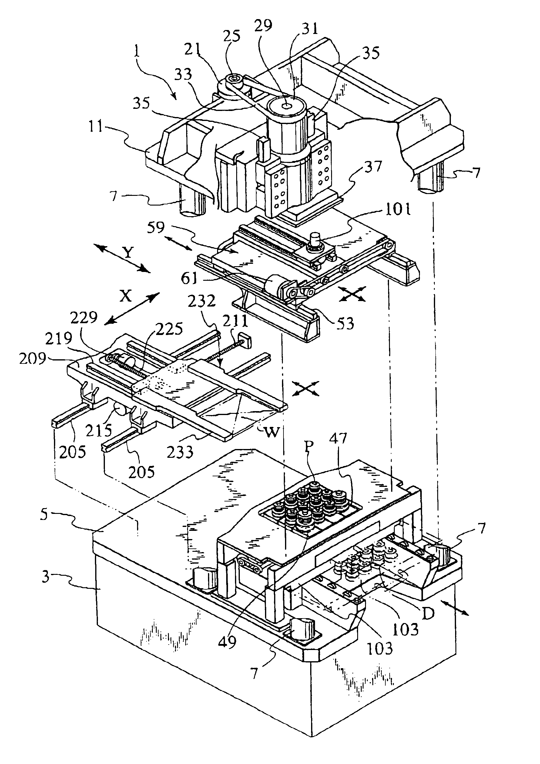
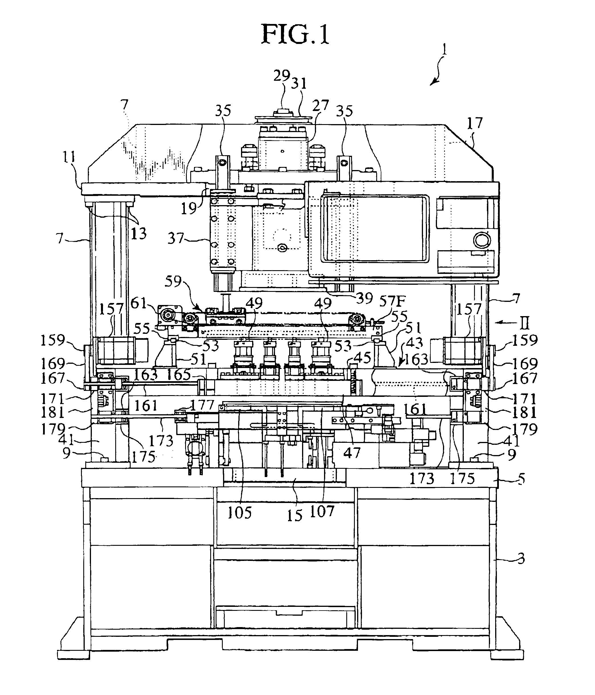
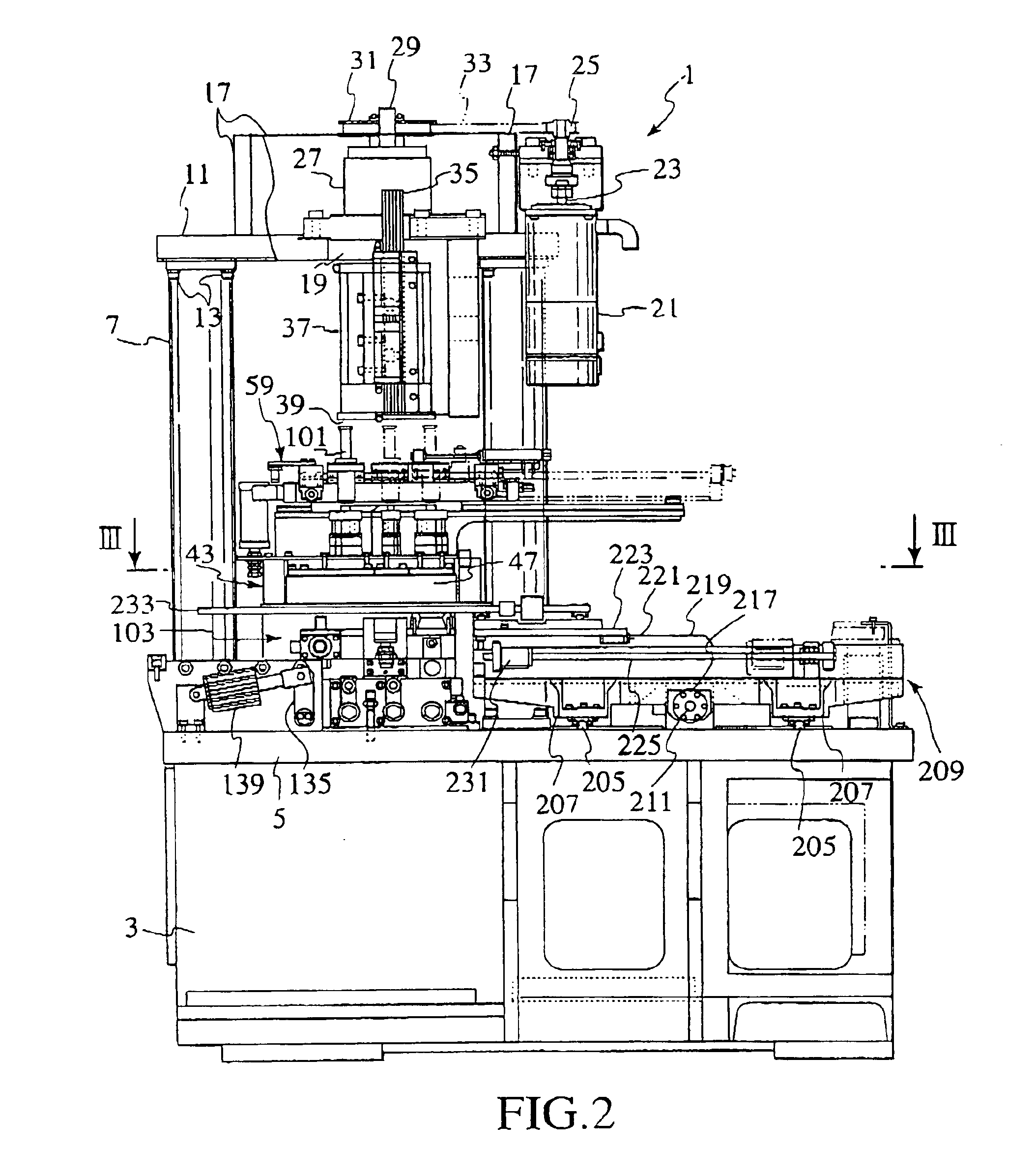
[0041]FIGS. 1 to 3 show an entire punch press 1 according to the invention. In this precise punch press 1, a structure which suppresses bending and vibration of the entire punch press 1 during presswork as small as possible is employed. That is, a pedestal 3 is provided at its upper surface with a thick base plate 5. Four rigid and thick columns 7 are fixed to front, rear, left and right ends of the base plate 5 through bolts 9. A ceiling frame 11 is fixed to upper sides of the columns 7 through bolts 13. A recess 15 (see FIG. 7) is formed in a front central portion of the base plate 5. A space is secured in a lower surface of an under-mentioned die holder to facilitate an operator's die-exchanging operation.

[0042]Reinforcing ribs 17 are provided on front, rear, left and right portions of an upper surface of the ceiling frame 11. The reinforced ceiling frame 11 is provided at its...


PUM


Abstract

In a cube space having high rigidity, the following members are provided: a die holder (103) which can be pulled out forward, a punch holder (47) fixed to a separate bridge structure, a striker which can be positioned in an XY plane for selecting a desired punch P, a striker supporting frame (59) which can be positioned in the XY plane for selecting a desired punch P and which can slide in a horizontal direction, and a clamp device (232) having clamp arms (233) which are provided with a vertically movable ram (37) and which can enter between the punch holder (47) and the die holder (103) and which hold the opposed ends of the workpiece W. Therefore, it is possible to constitute a punch press (1) which is suitable for precise machining of a thin plate and in which tools can easily be exchanged.

Description

[0001]This application is a 35 USC 371 of PCT / JP02 / 00088 filed Jan. 10, 2002.TECHNICAL FIELD[0002]The present invention relates to a punch press in which a striker strikes a punch held by a punch holder for carrying out punching work in cooperation with a die held by a die holder.BACKGROUND ART[0003]As conventional punch presses for selecting tools, two types punch presses are known, i.e., a type I in which a striker is fixed and a tool placed on a turret moves, and a type II in which the striker moves and the tool is fixed.[0004]The prior art in type I is an example of a turret punch press in which a tool is placed on a rotation turret. Japanese Utility Model Publication No. H7-47140 discloses a method in which a single striker which straightforwardly moves selectively strikes two tools. That is, rotation positioning of a turret and straightforward movement of the striker are combined to finally select a tool.[0005]It can be said that the prior art of type II is inferior in stabili...

Claims


Application Information

Patent Timeline
IPC IPC(8): B21D37/04B21D28/24B30B15/02B21D43/00B21D43/10
CPCB21D28/24B30B15/028B21D37/04Y10T483/1729
Inventor TOKUNAGA, HIRONORI
Owner AMADA CO LTD
Why Eureka
Try Eureka