Compressor and air conditioner

A technology in compressors and spaces, applied in the field of compressors, can solve problems such as the inability to guarantee the volume and quality of the compressor, the large volume and high quality of the compressor, and achieve the effect of reducing the structural volume, reducing the quality, and reducing the quality

Pending Publication Date: 2020-04-10
ZHUHAI GREE REFRIGERATION TECH CENT OF ENERGY SAVING & ENVIRONMENTAL PROTECTION
View PDF0 Cites 2 Cited by
  • Summary
  • Abstract
  • Description
  • Claims
  • Application Information

AI Technical Summary

Problems solved by technology

[0007] Therefore, the technical problem to be solved by the present invention is to overcome the compressor in the prior art due to the installation of a gas-liquid separator or an oil separator, which will cause the compressor to be too large in volume and quality, which cannot ensure that both gas-liquid separation and While separating oil and gas, it can effectively reduce the volume and quality defects of the compressor, thereby providing a compressor and an air conditioner

Method used


Image

  • Compressor and air conditioner
  • Compressor and air conditioner
  • Compressor and air conditioner

Examples


Embodiment 1

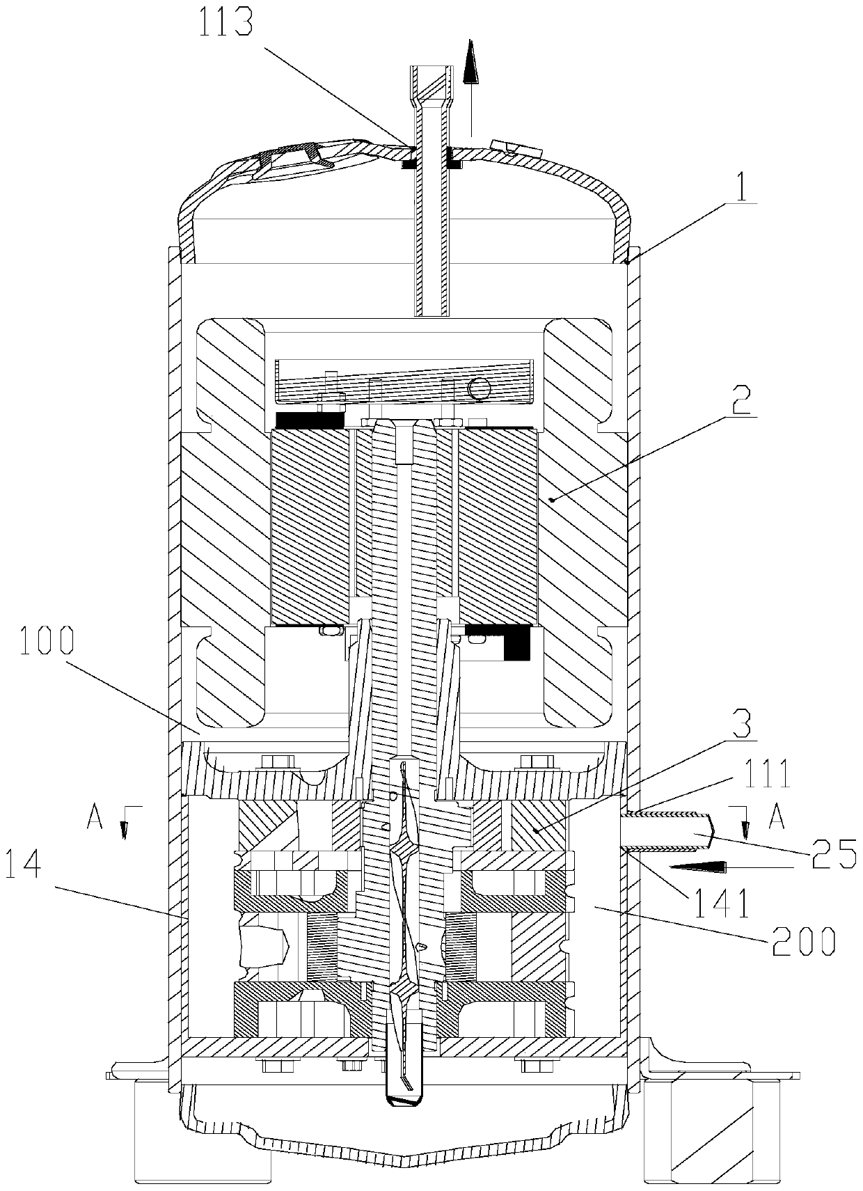
[0057] Example as Figure 1-7b As shown, the present invention provides a compressor, which includes:

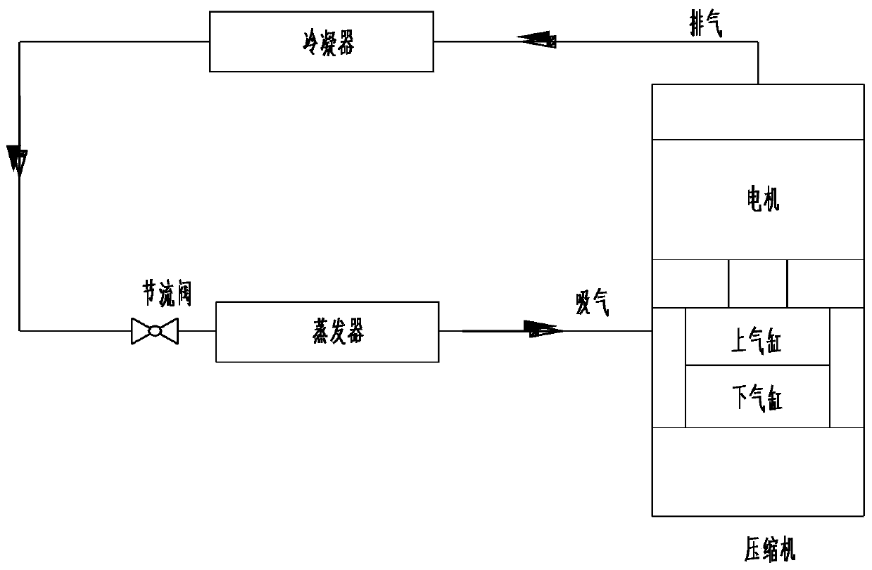
[0058] The present invention has embodiments as follows: the air-conditioning system of high back pressure two-stage compressor application, such as figure 1 As shown, the mixed refrigerant that flows into the compressor through the evaporator enters the cavity outside the pump body and undergoes gas-liquid separation, and then is sucked by the lower cylinder to compress the refrigerant once and discharge it into the cavity of the lower flange and the lower partition. Then it enters the upper cylinder through the flow hole of the pump body; the upper cylinder compresses the refrigerant twice to form a high-temperature and high-pressure gaseous state and discharges it into the compressor shell, where it becomes a low-temperature and high-pressure gas-liquid mixed refrigerant through the condenser, and then passes through the throttle valve After throttling and reducing press...

Embodiment 2

[0083] Embodiment two, such as Figure 8-10b As shown, preferably,

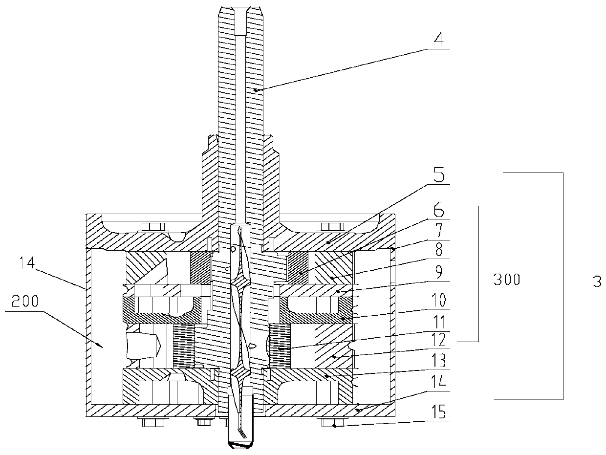
[0084] The pump body 300 also includes a crankshaft 4, and at least one helical partition 20 is disposed in the pump body cavity 200, and the spiral partition 20 is rotated in the opposite direction to the crankshaft 4. Such as Figure 8 As shown, the main difference between Embodiment 2 and Embodiment 1 is: as Figure 8 Shown, upper cylinder 8, upper dividing plate 9, lower dividing plate 10, lower cylinder 12, lower flange 13 cancels the helical groove 18 that is set around crankshaft 4. Such as Figure 9 As shown in Figure 10, the lower flange cover 14 is provided with a spiral partition 20 opposite to the rotation direction of the crankshaft 4, which enhances the spiral rotation guiding effect of the inner cavity of the lower flange cover 14 on the refrigerant.

[0085] Preferably,

[0086] When the flange includes a lower flange 13 and a lower flange cover 14, and the lower flange cover 14 is a cyli...

Embodiment 3

[0090] Such as Figure 11 As shown, the upper cylinder 8, the upper partition 9, the lower partition 10, the lower cylinder 12, and the lower flange 13 are provided with a spiral groove 18 around the crankshaft 4, and the lower flange cover 14 is provided with a spiral groove opposite to the rotation direction of the crankshaft 4. The separator 20 further effectively improves the spiral rotation guiding effect of the inner cavity of the lower flange cover 14 on the refrigerant, that is, it has a spiral groove and a spiral separator at the same time.


PUM


Abstract

The invention provides a compressor and an air conditioner. The compressor comprises a shell body assembly (1), a pump body assembly (3) is arranged in the shell body assembly (1), a shell body cavity(100) is formed in the shell body assembly (1), a pump body cavity (200) sealed with the shell body cavity (100) is formed in the pump body assembly (3), and thus fluid entering the pump body cavity(200) can be subjected to gas-liquid separation or oil-gas separation. According to the compressor and the air conditioner, the gas-liquid separation can be completed, meanwhile a structure of a gas-liquid separator is further effectively omitted, the oil-gas separation is completed, meanwhile a structure of an oil-gas separator is further effectively omitted, the structure volume can also be greatly decreased, the mass is decreased, it can be guaranteed that the gas-liquid separation and oil-gas separation can be conducted, and meanwhile the volume and mass of the compressor can be effectively decreased.

Description

technical field [0001] The invention belongs to the technical field of compressors, and in particular relates to a compressor and an air conditioner. Background technique [0002] There are mainly two types of rolling rotor compressors for existing refrigeration systems: one is a high-back pressure compressor with a high-pressure refrigerant in the compressor housing assembly, and the other is a high-back pressure compressor with a low-pressure refrigerant in the compressor housing assembly. Low back pressure compressor. [0003] The high back pressure compressor uses an external liquid separator on the suction pipe to separate the gas and liquid for the mixed refrigerant sucked in, so as to ensure that the suction of the pump body does not cause liquid entrainment, thereby ensuring the reliability of the compressor. However, the compressor With the assembly of the liquid separator, its volume and mass increase, and at the same time, the liquid separator will generate noise...

Claims


Application Information

Patent Timeline
Patent Type & Authority Applications(China)
IPC IPC(8): F04C18/356F04C23/00F04C29/00F04C29/02F04C29/04F04C29/06F25B31/00
CPCF04C18/3562F04C23/001F04C29/0021F04C29/026F04C29/04F04C29/06F04C2240/10F04C2240/80F25B31/00
Inventor 魏会军邓罡罗惠芳陈圣吴健柯达俊巩庆霞
Owner ZHUHAI GREE REFRIGERATION TECH CENT OF ENERGY SAVING & ENVIRONMENTAL PROTECTION
Why Eureka
Try Eureka