Positioning device and method on basis of inertia and visual features, and robot

A positioning device and visual feature technology, applied in the field of positioning devices based on inertial data and visual features, can solve the problems of camera lens collision, increased camera angle, easy blocking of the camera, etc., so as to improve positioning accuracy, improve navigation efficiency, The effect of shortening the feature search time

Pending Publication Date: 2018-09-18
AMICRO SEMICON CORP
View PDF9 Cites 8 Cited by
  • Summary
  • Abstract
  • Description
  • Claims
  • Application Information

AI Technical Summary

Problems solved by technology

[0003] In the existing visual sweeper products, the camera is placed in front of the machine. Generally, it needs to protrude slightly to obtain a better viewing angle. However, this will easily cause the camera lens to be touched by some objects that are difficult to detect, and it is easy to scratch. Flower lenses; and there are generally more sensors placed in front of the machine, for example, many machines have collision bars and cylindrical 360-degree infrared receivers, which are easy to block the camera, resulting in the need to increase the angle of the camera

Method used


Image

  • Positioning device and method on basis of inertia and visual features, and robot
  • Positioning device and method on basis of inertia and visual features, and robot
  • Positioning device and method on basis of inertia and visual features, and robot

Examples


Embodiment Construction

[0031] The specific embodiment of the present invention will be further described below in conjunction with accompanying drawing:

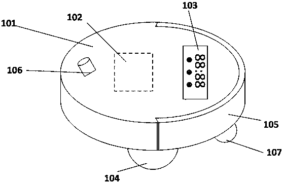
[0032] A positioning device based on inertial data and visual features in the embodiment of the present invention is implemented in the form of a robot, including mobile robots such as sweeping robots and AGVs. It is assumed below that the obstacle avoidance device is installed on the sweeping robot. However, those skilled in the art will appreciate that the configurations according to the embodiments of the present invention can be extended to be applied to mobile terminals, in addition to being used specifically for mobile robots.

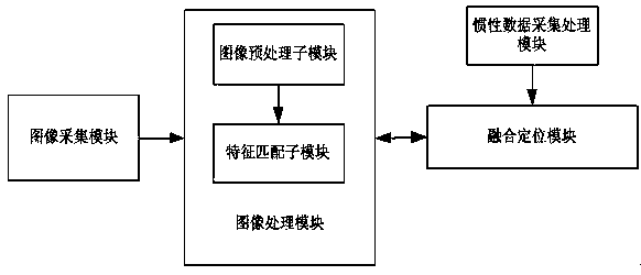
[0033] The present invention provides a positioning device based on inertial data and visual features, the visual positioning device is a movable visual positioning device, such as figure 1 As shown, it includes an image acquisition module, an image processing module, an inertial data acquisition module and a fusion...


PUM


Abstract

The invention discloses a positioning device and method on the basis of inertia data and visual features, and a robot. The positioning device is a movable visual positioning device and comprises an image acquisition module, an image processing module, an inertia data acquisition processing module and a mixed positioning module, wherein cameras of the image acquisition module face downwards and areput in the preset position of the positioning device and used for avoiding collision of an obstacle during advancing; the image processing module comprises an image pre-processing submodule and a feature matching submodule and used for processing acquired image data; the inertia data acquisition processing module is used for sensing the rotary angle information, accelerated speed information andtranslational speed information of an inertia sensor in real time; and the mixed positioning module is used for mixing the environment information obtained by all sensor modules so as to achieve positioning. Compared with the prior art, the cameras are effectively prevented from being blocked by the obstacle during advancing of a machine, feature-matched image data and inertia data are mixed, a landmark is updated in combination with the relative position relation, then the feature matching result is more accurate, and the robustness of a positioning algorithm is enhanced.

Description

technical field [0001] The invention relates to a positioning method and device, in particular to a positioning device, a positioning method and a robot based on inertial data and visual features. Background technique [0002] To achieve intelligentization of robots, a basic technology is to be able to position and walk by itself, and indoor navigation technology is the key technology. At present, indoor navigation technologies include inertial sensor navigation, laser navigation, visual navigation, radio navigation, etc., and each technology has its own advantages and disadvantages. Inertial sensor navigation uses gyroscopes, odometers, etc. for navigation and positioning. The price is low, but there is a problem of long-term drift; laser navigation has high accuracy, but the price is relatively high, and life is also a problem; traditional visual navigation, the calculation is complicated , the performance requirements of the processor are relatively high, the power consu...

Claims


Application Information

Patent Timeline
Patent Type & Authority Applications(China)
IPC IPC(8): B25J9/16B25J19/00B25J19/04
CPCB25J9/1697B25J19/00B25J19/04
Inventor 赖钦伟
Owner AMICRO SEMICON CORP
Why Eureka
Try Eureka