
Distribution box with auxiliary installation structure

A technology of installation structure and distribution box, applied in the direction of electrical components, substation/switch layout details, etc., can solve the problems of inconvenience, unfavorable maintenance efficiency, time-consuming and labor-intensive, etc., and achieve the effect of high convenience

Active Publication Date: 2021-07-09
JIANGSU ELECTRIC POWER CO
View PDF8 Cites 1 Cited by
  • Summary
  • Abstract
  • Description
  • Claims
  • Application Information

AI Technical Summary

Problems solved by technology

[0004] The distribution box sometimes needs to be installed at a higher position due to environmental restrictions, and the existing device needs to be fixed by the staff to provide reliable support for it to be easily installed and fixed, which will be very time-consuming and laborious. Furthermore, the current Although there is a device that improves the convenience for the staff to install electrical equipment in it, as the electrical equipment is a relatively high-density equipment, the staff needs to overhaul it frequently, and in the process of overhauling the device, the staff needs to It is extremely inconvenient to remove the electrical equipment, which is not conducive to improving the efficiency of maintenance. In view of this, we propose a distribution box with an auxiliary installation structure

Method used


Image

  • Distribution box with auxiliary installation structure
  • Distribution box with auxiliary installation structure
  • Distribution box with auxiliary installation structure

Examples


Embodiment Construction

[0025] In describing the present invention, it should be understood that the terms "center", "longitudinal", "transverse", "length", "width", "thickness", "upper", "lower", "front", " Orientation indicated by rear, left, right, vertical, horizontal, top, bottom, inside, outside, clockwise, counterclockwise, etc. The positional relationship is based on the orientation or positional relationship shown in the drawings, and is only for the convenience of describing the present invention and simplifying the description, rather than indicating or implying that the referred device or element must have a specific orientation, be constructed and operated in a specific orientation, Therefore, it should not be construed as limiting the invention.

[0026] In the description of the present invention, "plurality" means two or more, unless otherwise specifically defined.

[0027] In the description of the present invention, it should be noted that, unless otherwise specified and limited, t...


PUM


Abstract

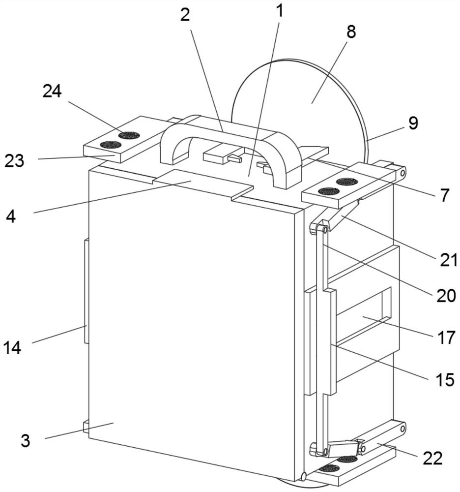
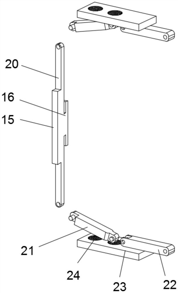
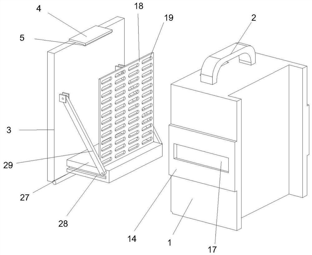
The invention discloses a distribution box with an auxiliary installation structure, and belongs to the technical field of distribution boxes. The distribution box with the auxiliary installation structure comprises a box body, a U-shaped handle is fixedly arranged in the middle of the top surface of the box body, a box door is hinged to the lower end of the wall of the box body, a top plate is fixedly arranged in the middle of the top surface of the box door, a clamping block is fixedly arranged at the rear end of the bottom surface of the top plate, and a clamping groove is formed in the top surface of the box body and corresponds to the clamping block. Two connecting plates are symmetrically and fixedly arranged on the rear portions of the upper outer wall and the lower outer wall of the box body, a base is fixedly arranged between the rear ends of the two connecting plates located on the same side, a suction cup is fixedly arranged on the rear wall of the base, a pull rod is fixedly arranged in the middle of the front wall of the suction cup, block grooves are formed in the front ends of the inner walls of the connecting plates, and limiting blocks are fixedly arranged on the inner walls of the block grooves through compression springs. Sliding blocks are fixedly arranged in the middles of the inner side walls of the push plates. The problem that a traditional box body fixing mode is troublesome and inconvenient to support a box body is solved, installation of the box body by workers is facilitated, the installation efficiency is also improved, and the practicability is high.

Description

technical field [0001] The invention relates to the technical field of distribution boxes, more specifically, to a distribution box with an auxiliary installation structure. Background technique [0002] The distribution box is used to install power switches and safety devices. The structure of the power distribution box is relatively simple, mainly used for terminal power distribution, and it is the first-level power distribution equipment in the power system. The distribution box can be a power socket and a plurality of power output circuits, and the power output circuit is drawn from the distribution box to each electrical load, and the circuit can be connected or disconnected by means of a manual or automatic switch during normal operation. [0003] After searching, the patent with the publication number CN212343146U discloses a distribution box with an auxiliary installation structure. The electrical installation board can slide in the distribution box to facilitate th...

Claims


Application Information

Patent Timeline
Patent Type & Authority Applications(China)
IPC IPC(8): H02B1/46H02B1/40H02B1/48H02B1/42H02B1/36H02B1/44
CPCH02B1/46H02B1/40H02B1/48H02B1/42H02B1/36H02B1/44
Inventor 戴洪
Owner JIANGSU ELECTRIC POWER CO
Learn More