A minimally invasive lung blocker for cardiothoracic surgery
A technique of minimally invasive surgery and surgery, which is applied in the field of medical devices, can solve the problems of physical exertion of surgical assistants, affecting the exposure of the surgical site, and the single function of the lung blocker, so as to improve the efficiency of surgery, reduce the risk of surgery, and reduce physical strength.
- Summary
- Abstract
- Description
- Claims
- Application Information
AI Technical Summary
Problems solved by technology
Method used
Image
Examples
Embodiment 1
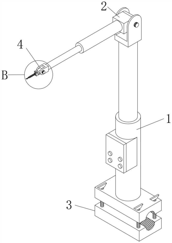
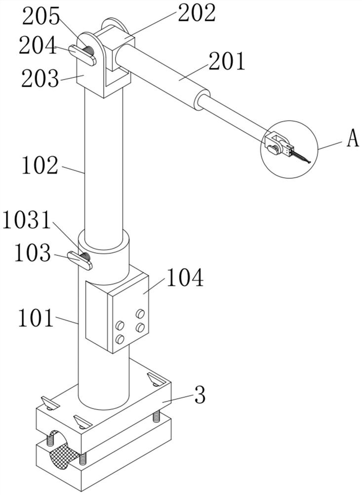
[0044] like figure 1 , figure 2 and Image 6 As shown, a minimally invasive lung blocker for cardiothoracic surgery according to an embodiment of the present invention includes a lifting mechanism 1 , a rotating mechanism 2 , a fixing mechanism 3 , a fine-tuning mechanism 4 and an expansion mechanism 5 .
[0045] Among them, such as figure 1 and figure 2 As shown, the lifting mechanism 1 includes a cylindrical sleeve 101 and a cylindrical insertion rod 102, the lower end of the cylindrical insertion rod 102 is inserted into the interior of the cylindrical sleeve 101, and the outer wall of the upper end of the cylindrical sleeve 101 is fixed A first threaded rod 1031 for fixing the cylindrical insertion rod 102 is installed, and one end of the first threaded rod 1031 is fixedly connected with a first knob block 103;
[0046] Among them, such as Figure 1-Figure 2 as well as Figure 8 As shown, the rotating mechanism 2 includes an electric push rod 201, a first rotating ...
Embodiment 2
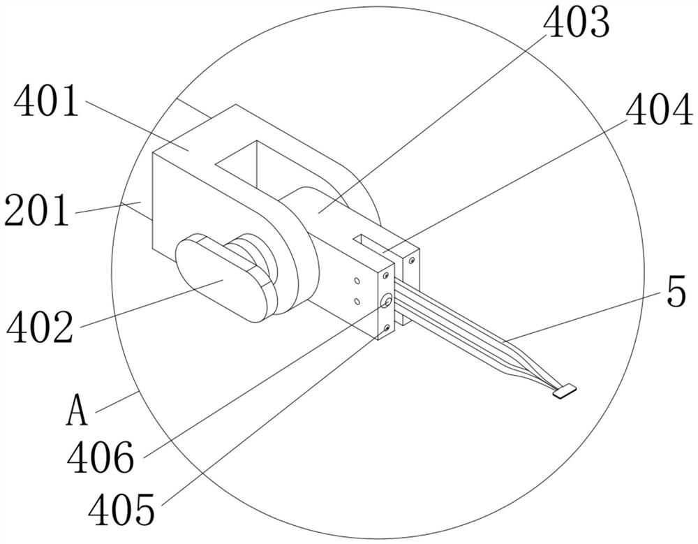
[0058] like Figure 2-Figure 3 As shown, the difference between this embodiment and Embodiment 1 is that the end face of the second rotating block 403 away from the third threaded rod 407 is fixedly installed with an LED fill light 405, and the LED fill light 405 is set not less than two indivual.
[0059] By adopting the above technical solution, when the illuminance of the operating environment is low, the brightness can be increased by turning on the LED fill light 405, which is convenient for the operator to operate without adding other lighting tools.
Embodiment 3
[0061] like figure 2 and Figure 7 As shown, the difference between this embodiment and Embodiment 2 is that the control box 104 is fixedly installed on the outer wall of the cylindrical sleeve 101, the controller 1042 is fixedly installed inside the control box 104, and the signal output ends of the controller 1042 are respectively It is electrically connected with the electric control end of the LED fill light 405 , the electric control end of the electric push rod 201 and the electric control end of the servo motor 501 .
[0062] By adopting the above technical solution, the control of the device by the controller 1042 is facilitated, and the operation of the device by the user is simplified.
PUM
 Abstract
Description
Claims
Application Information
 - R&D
- Intellectual Property
- Life Sciences
- Materials
- Tech Scout
- Unparalleled Data Quality
- Higher Quality Content
- 60% Fewer Hallucinations
Browse by: Latest US Patents, China's latest patents, Technical Efficacy Thesaurus, Application Domain, Technology Topic, Popular Technical Reports.
© 2025 PatSnap. All rights reserved.Legal|Privacy policy|Modern Slavery Act Transparency Statement|Sitemap|About US| Contact US: help@patsnap.com


