Raw material grinding equipment for solid beverage production

A technology of solid beverages and raw materials, applied in grain processing, etc., can solve problems such as troublesome, laborious, easy to be knocked down, occupying space, etc., and achieve the effect of easily unlocking the device

Active Publication Date: 2021-07-13
江西诺泰生物科技有限公司
View PDF8 Cites 2 Cited by
  • Summary
  • Abstract
  • Description
  • Claims
  • Application Information

AI Technical Summary

Problems solved by technology

[0003] In the existing raw material grinding technology for solid beverage production, the motor is generally used to drive the grinding piece to rotate at a high speed, and the grinding piece is moved until it touches the raw material to complete the grinding. However, when the equipment is in operation, it may shake randomly under the impact of force and affect Grinding, and secondly, the equipment is only placed on the table for material grinding, which not only takes up space, but is also easy to be knocked down, and once the equipment is fixed somewhere, when there is no need for grinding, it is also troublesome and laborious to remove the equipment

Method used


Image

  • Raw material grinding equipment for solid beverage production
  • Raw material grinding equipment for solid beverage production
  • Raw material grinding equipment for solid beverage production

Examples


Embodiment 1

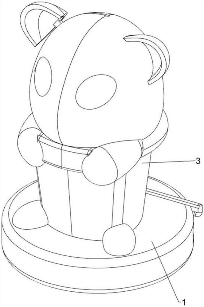
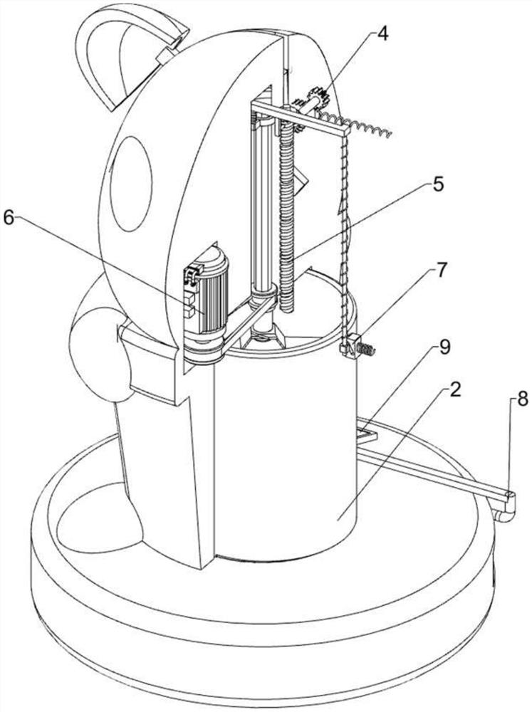
[0028] like Figure 1 to Figure 5 As shown, this embodiment discloses a raw material grinding equipment for solid beverage production, including a support plate 1, a placement cup 2, a housing 3, a drive mechanism 4, a lifting mechanism 5 and a grinding mechanism 6, and the upper middle of the support plate 1 is threaded Cooperate with a placement cup 2, the upper middle of the support plate 1 is covered with a housing 3, the placement cup 2 is located in the housing 3, the upper rear side of the housing 3 is provided with a driving mechanism 4, and the upper middle of the housing 3 is connected to the driving mechanism 4 A lifting mechanism 5 is arranged between them, and a grinding mechanism 6 is arranged between the front side of the middle part of the housing 3 and the lifting mechanism 5 .

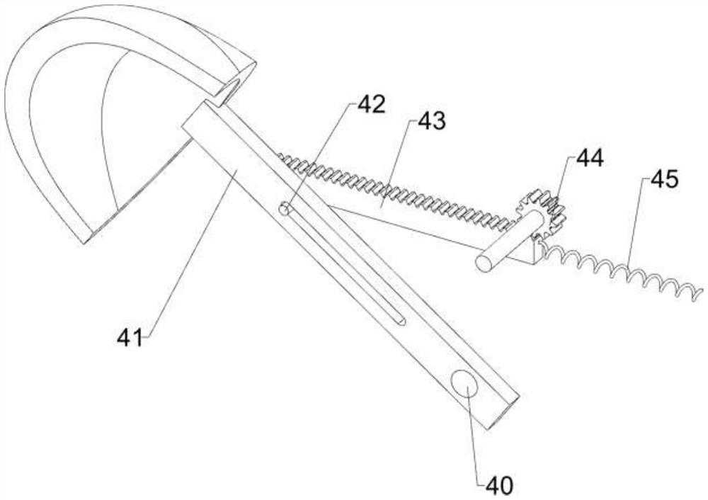
[0029] The driving mechanism 4 includes a first rotating shaft 40, a rotating rod 41, a slide bar 42, a rack 43, a first gear 44 and a first spring 45, and the upper rear side of the ...

Embodiment 2

[0034] Such as figure 2 , Figure 6 ~ Figure 9 As shown, in some embodiments, a clamping assembly 7 is also included. The clamping assembly 7 includes a guide rod 70, a third spring 71, a contact block 72, a clamping block 73 and a fourth spring 74. The lower part of the special-shaped rod 52 The left and right sides are connected with guide rods 70, and the lower side of the guide rods 70 is slidably connected with a contact block 72. A third spring 71 is connected between the contact block 72 and the special-shaped rod 52, and the third spring 71 is sleeved on the guide rod 70. Above, the left and right sides of the lower part of the housing 3 are slidably connected with clamping blocks 73, the clamping blocks 73 cooperate with the contact block 72 and the placement cup 2, and a fourth clamping block 73 is connected with the housing 3. spring 74.

[0035] When the special-shaped rod 52 moves downward, it will drive the guide rod 70 and the contact to move downward, thereb...


PUM


Abstract

The invention discloses raw material grinding equipment for solid beverage production. The raw material grinding equipment comprises a supporting plate and the like. A containing cup is matched with the middle of the upper portion of the supporting plate through threads, the middle of the upper portion of the supporting plate is covered with a shell, the containing cup is located in the shell, a driving mechanism is arranged on the rear side of the upper portion in the shell, and a lifting mechanism is arranged between the middle of the upper portion in the shell and the driving mechanism. The raw material grinding equipment for solid beverage production has the advantages that the shell is stable, the shell is prevented from shaking randomly in the grinding process, the equipment is easily fixed to the edge of a table, the portability of the equipment is embodied, and the equipment is more easily unlocked.

Description

technical field [0001] The invention relates to a grinding device, in particular to a raw material grinding device for solid beverage production. Background technique [0002] Solid beverage refers to a kind of sugar, milk and dairy products, eggs or egg products, fruit juice or edible plant extracts, etc. When preparing solid beverages, some of its raw materials need to be ground into powder for addition. [0003] In the existing raw material grinding technology for solid beverage production, the motor is generally used to drive the grinding piece to rotate at a high speed, and the grinding piece is moved until it touches the raw material to complete the grinding. However, when the equipment is in operation, it may shake randomly under the impact of force and affect Grinding, and secondly, the equipment is only placed on the table for material grinding, which not only takes up space, but is also easy to be knocked down, and once the equipment is fixed somewhere, when there...

Claims


Application Information

Patent Timeline
IPC IPC(8): B02C13/18B02C13/28B02C13/30B02C13/26
CPCB02C13/18B02C13/2804B02C13/30B02C13/26
Inventor 祝精斌
Owner 江西诺泰生物科技有限公司
Why Eureka
Try Eureka