Flood prevention device

A flood control device and box technology, applied in dikes, marine engineering, construction, etc., can solve the problems of non-reusable sandbags and wooden boards, poor overall effect, strong manual labor, etc., to achieve good water blocking effect, convenient disassembly, The effect of adding weight

Active Publication Date: 2021-10-29
王进
View PDF7 Cites 0 Cited by
  • Summary
  • Abstract
  • Description
  • Claims
  • Application Information

AI Technical Summary

Problems solved by technology

When there is an emergency and flood control is required, sandbags or wooden boards are usually used for blocking, but sandbags or wooden boards are relatively independent individuals, and the overall effect is poor in the process of use
The sandbags are heavy, and transporting the sandbags to the flood control site requires a lot of manual labor; both sandbags and wooden boards have the problem that they cannot be reused, resulting in a waste of resources

Method used


Image

  • Flood prevention device
  • Flood prevention device
  • Flood prevention device

Examples


Embodiment 1

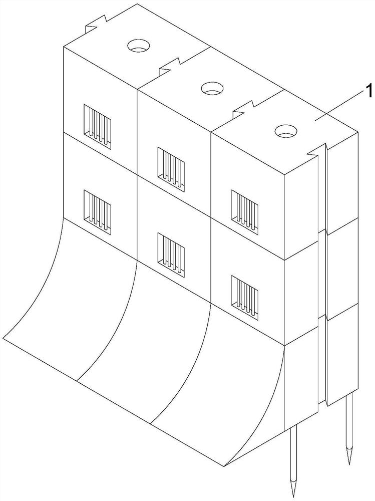
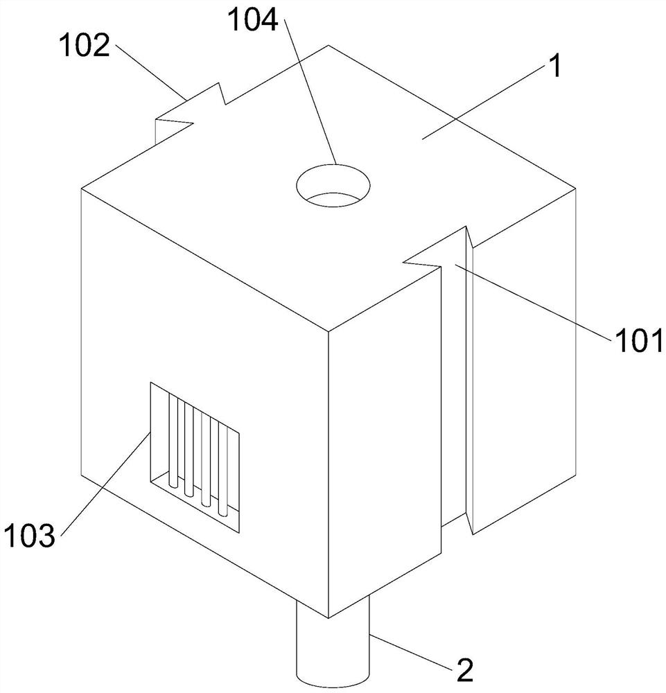
[0035] The flood control device of the present invention includes several box units 1 arranged horizontally and vertically, the box unit 1 is a hollow structure, the upper end of the box unit 1 is provided with a water inlet 104, and the lower end of the box unit 1 is provided with a guide pipe 2 , the guide tube 2 communicates with the inside of the box unit 1, the outer wall of one side of the box unit 1 is provided with a limiting groove 101, and the other side of the box unit 1 is provided with a The limit protrusion 102, the side wall of the box unit 1 is provided with an overflow port 103, and the inside of the box unit 1 is provided with a baffle plate 4 that can move up and down, and the baffle plate 4 can block the flow port 103.

[0036]After adopting the above-mentioned technical solution: several box units 1 of the present invention are arranged horizontally and vertically, and the box units 1 adjacent in the horizontal direction are connected to each other through ...

Embodiment 2

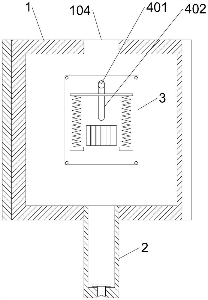
[0038] This embodiment is further optimized on the basis of Embodiment 1 as follows: the inside of the box unit 1 is provided with a splint 3, and the splint 3 forms a sandwich with one side of the inner wall of the box unit 1, and the interlayer covers the flow port 103, and the splint 3. There is a communication hole opposite to the flow port 103. The baffle plate 4 is set in the interlayer and can move up and down in the interlayer. The upper end side wall of the baffle plate 4 is provided with a guide column 401, and the guide column 401 runs through the splint 3, and the splint 3 A relief groove 402 is provided to facilitate the lifting and moving of the guide column 401. The side wall of the baffle plate 4 is provided with a first segment 501 on the left side of the flow port 103, a second segment 502 on the upper side of the flow port 103 and The third segment 503 located on the right side of the flow port 103, the fourth segment 504 located on the lower side of the flow...

Embodiment 3

[0041] This embodiment is further optimized on the basis of Embodiment 1 as follows: the outer wall of the splint 3 is provided with a lifting plate 8 and a fixed plate 10 located below the lifting plate 8, and a return spring is arranged between the fixed plate 10 and the lifting plate 8 9. The lifting plate 8 and the guide column 401 are connected to each other, the guide pipe 2 of the upper box unit 1 can enter the interior of the lower box unit 1 through the water inlet 104 of the lower box unit 1, and guide the flow The lower end of the tube 2 can contact the guide post 401 and force the guide post 401 to move downward.

[0042] After adopting the above technical scheme: the lifting plate 8 arranged on the outer wall of the splint 3 is connected to the guide column 401, and under the action of the return spring 9, the initial state of the baffle plate 4 is located above the flow port 103, when the vertical direction is adjacent When the box unit 1 is assembled, the guide ...


PUM


Abstract

The invention discloses a flood prevention device, and relates to the technical field of flood prevention devices. The flood prevention device comprises a plurality of box body units which are transversely and longitudinally arranged, each box body unit is of a hollow structure, a water inlet is formed in the upper end of each box body unit, a flow guide pipe is arranged at the lower end of each box body unit, and flow guide pipes communicate with the interiors of the box body units; a limiting groove is formed in the outer wall of one side of each box body unit, a limiting protrusion matched with the limiting groove is arranged on the other side of each box body unit, an overflowing opening is formed in the side wall of each box body unit, a baffle capable of moving in a lifting mode is arranged in each box body unit, and each baffle can block the corresponding overflowing opening. According to the flood prevention device, the flood prevention device is composed of the multiple box body units, the weight of each box body unit is lighter than that of a sandbag, and carrying is convenient; the integrality formed by splicing is high, and water retaining and flood prevention can be effectively achieved.

Description

technical field [0001] The invention relates to the technical field of flood control devices, in particular to a flood control device. Background technique [0002] Flood control is to prevent and mitigate flood disasters, related work carried out in flood forecasting, flood control dispatching, and flood control engineering application. When there is an emergency and flood control is required, sandbags or wooden boards are usually used for blocking, but sandbags or wooden boards are relatively independent individuals, and the overall effect is poor during use. The sandbags are heavy, and transporting the sandbags to the flood control site requires a lot of manual labor; both the sandbags and the wooden boards have the problem that they cannot be reused, resulting in a waste of resources. [0003] For this reason, urgently need a kind of flood prevention device, be made up of several box body units, the weight of single box body unit is lighter than sandbag, convenient to c...

Claims


Application Information

Patent Timeline
Patent Type & Authority Applications(China)
IPC IPC(8): E02B3/10
CPCE02B3/106
Inventor 王进
Owner 王进
Why Eureka
Try Eureka