Medical mask recycling and crushing equipment
A technology of crushing equipment and masks, applied in metal processing, grain processing, solid waste removal, etc., can solve problems such as poor recycling effect
- Summary
- Abstract
- Description
- Claims
- Application Information
AI Technical Summary
Problems solved by technology
Method used
Image
Examples
Embodiment 1
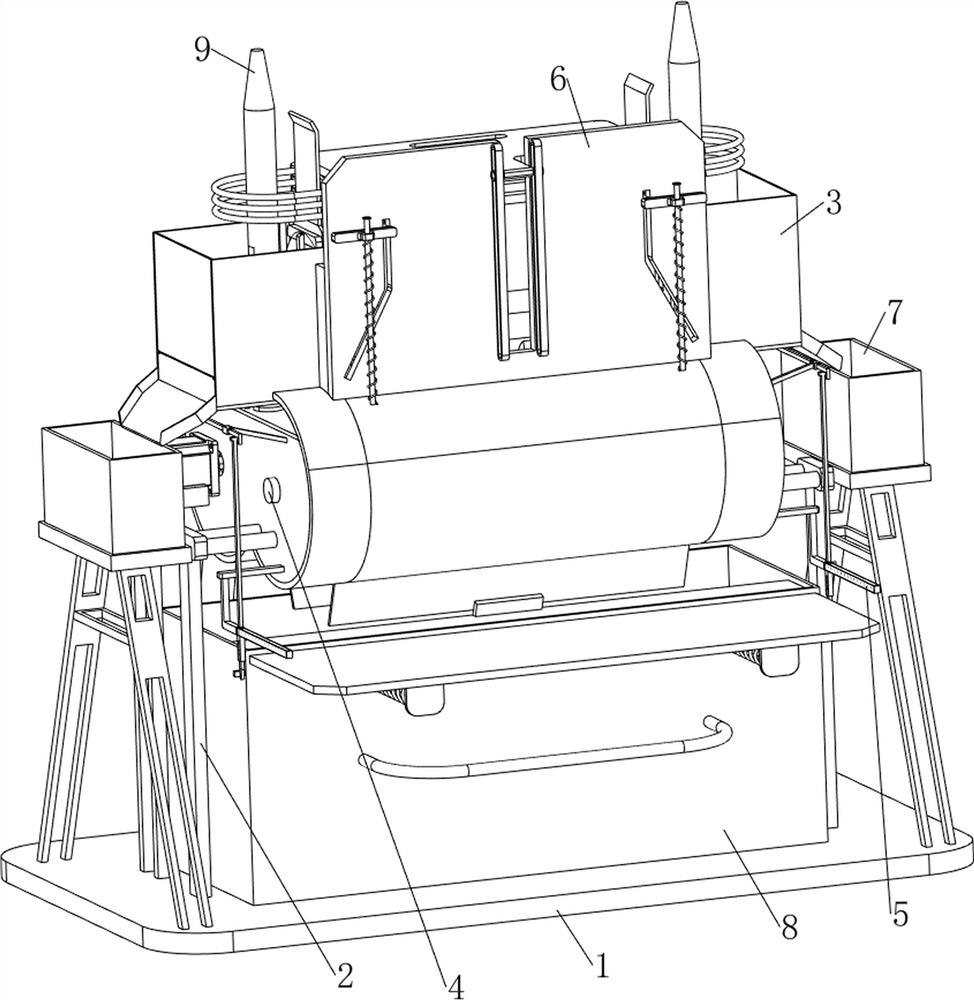
[0031] A kind of medical mask recycling crushing equipment, such as Figure 1-2 As shown, it includes a base plate 1, a support frame 10, a first support rod 2, a cutting mechanism 3 and a crushing mechanism 4, the upper part of the base plate 1 is provided with a support frame 10, and the upper part of the base plate 1 is symmetrically provided with a first support rod 2, The first support rods 2 on both sides are connected to the support frame 10, the upper part of the support frame 10 is provided with a cutting mechanism 3, and the cutting mechanism 3 is provided with a crushing mechanism 4.
[0032] When the user needs to recycle the mask, this device can be used. First, the mask that needs to be recycled is placed in the cutting mechanism 3, and the mask is cut by the cutting mechanism 3. After the cutting is completed, the cut is cut by the crushing mechanism 4. The final mask is crushed, and after the crushing is completed, the user can collect the fragments of the mask...
Embodiment 2
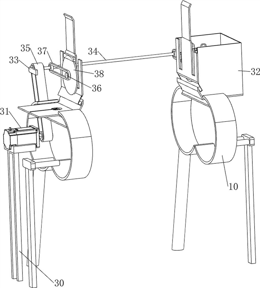
[0034] On the basis of Example 1, such as Figure 3-4 As shown, the cutting mechanism 3 includes a second support rod 30, a motor 31, a first collection frame 32, a support block 33, a first rotating shaft 34, a first transmission assembly 35, a second rotation shaft 36, a second transmission assembly 37 and a saw sheet 38, the left side of the bottom plate 1 top is provided with a second support rod 30, the second support rod 30 top is provided with a motor 31, and the support frame 10 top is symmetrically provided with a first collection frame 32, and the rear sides of the first collection frame 32 are arranged A supporting block 33 is provided, and a first rotating shaft 34 is rotatably arranged between the supporting blocks 33 on both sides, and a first transmission assembly 35 is connected between the first rotating shaft 34 and the output shaft of the motor 31, and the inner side of the first collecting frame 32 is uniform. The rotary type is provided with a second rotat...
Embodiment 3
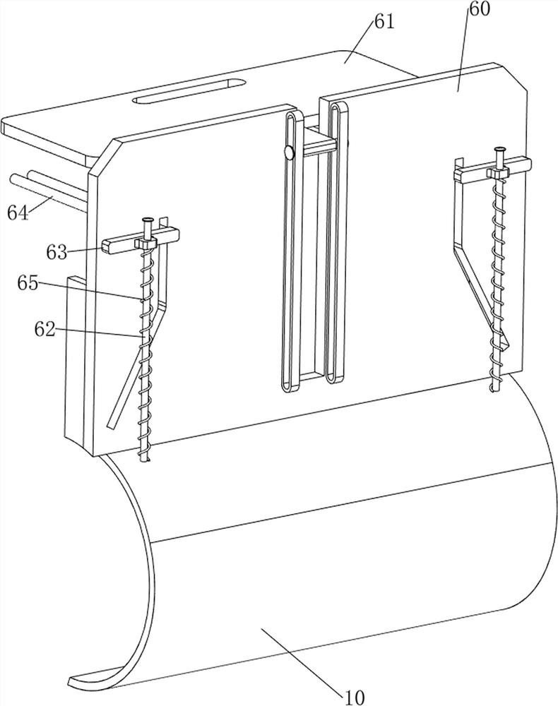
[0039] On the basis of Example 2, such as Figure 5-11As shown, it also includes a retrieving mechanism 5, and the retrieving mechanism 5 includes a first fixed plate 50, a sleeve 51, a first spring 52, a push column 53, a clamping rod 54, an L-shaped rod 55, a fixed rod 56, a movable Rod 57, guide frame 58, second spring 59 and telescopic assembly 510, the inside of first collecting frame 32 is all provided with first fixing plate 50, is connected with sleeve 51 on the first fixing plate 50, on the first collecting frame 32 The sliding type is provided with a push column 53, the push column 53 is connected with the sleeve 51, the first spring 52 is connected between the push column 53 and the first fixed plate 50, the first spring 52 is sleeved on the sleeve 51, and the push column 53 The bottom is provided with clamping bar 54, and the left and right sides of support frame 10 are all provided with L-shaped bar 55, and support frame 10 left and right sides are all provided wi...
PUM
 Abstract
Description
Claims
Application Information
 - R&D
- Intellectual Property
- Life Sciences
- Materials
- Tech Scout
- Unparalleled Data Quality
- Higher Quality Content
- 60% Fewer Hallucinations
Browse by: Latest US Patents, China's latest patents, Technical Efficacy Thesaurus, Application Domain, Technology Topic, Popular Technical Reports.
© 2025 PatSnap. All rights reserved.Legal|Privacy policy|Modern Slavery Act Transparency Statement|Sitemap|About US| Contact US: help@patsnap.com


