Punching equipment for sheet metal part machining and material collecting technology of punching equipment

A technology for sheet metal parts and punching, which is applied in the field of punching equipment for sheet metal parts processing and its material receiving process, can solve problems such as affecting the punching processing of workpieces and inconvenient cleaning of the volume.

Active Publication Date: 2021-07-13
上海通成企业发展有限公司
View PDF12 Cites 0 Cited by
  • Summary
  • Abstract
  • Description
  • Claims
  • Application Information

AI Technical Summary

Problems solved by technology

[0004] With regard to the related technologies mentioned above, the inventor believes that most of the waste generated by punching the workpiece is accumulated on the top wall of the workbench, and most of the waste is light in texture, small in size and It is inconvenient to clean up; when a certain amount of waste material is accumulated on the workbench, the waste material can easily prevent the workpiece from entering the inner cavity of the through hole smoothly, thereby affecting the defect that the subsequent workpiece is punched through the machine body

Method used


Image

  • Punching equipment for sheet metal part machining and material collecting technology of punching equipment
  • Punching equipment for sheet metal part machining and material collecting technology of punching equipment
  • Punching equipment for sheet metal part machining and material collecting technology of punching equipment

Examples


Embodiment Construction

[0039] The following is attached Figure 2-6 This application will be described in further detail.

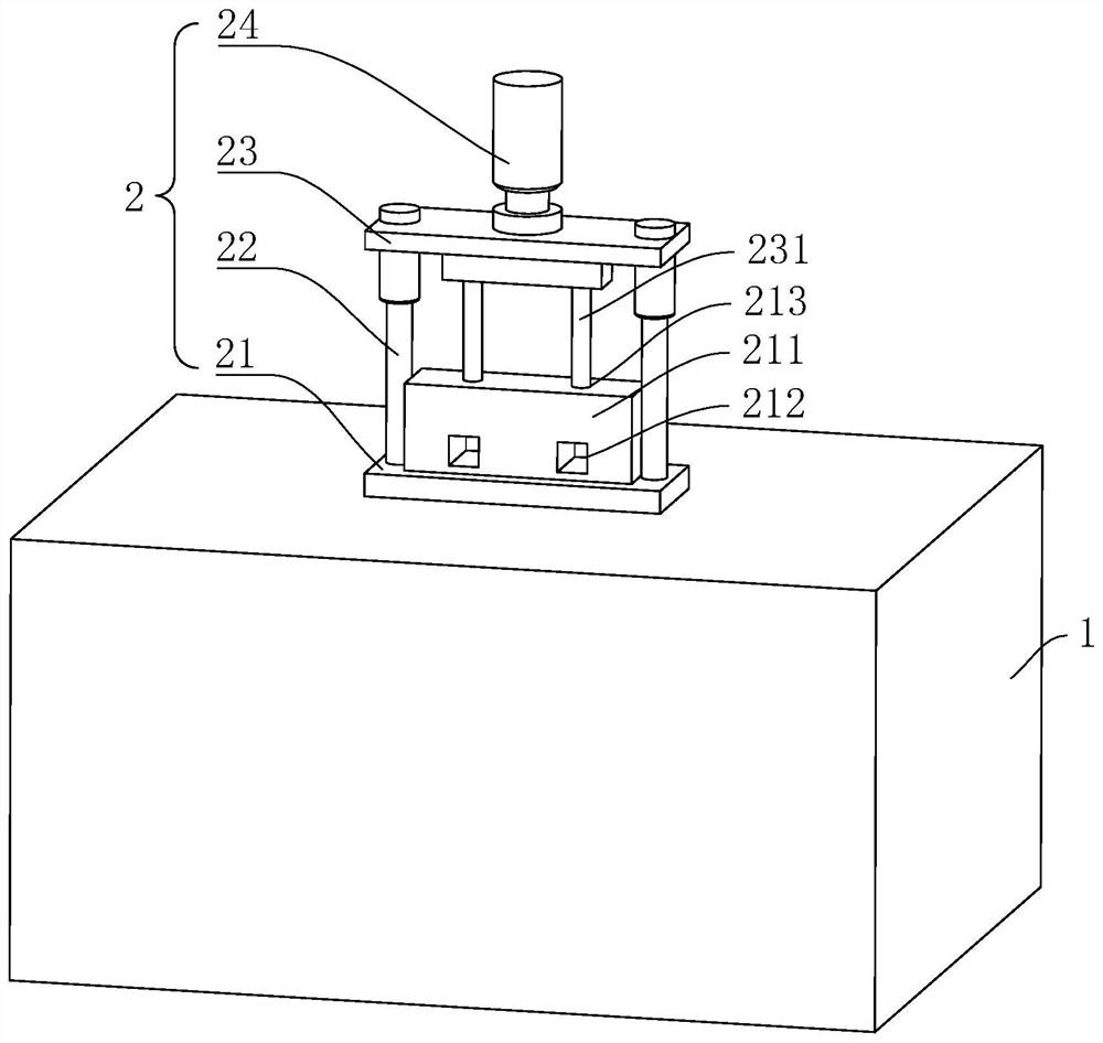
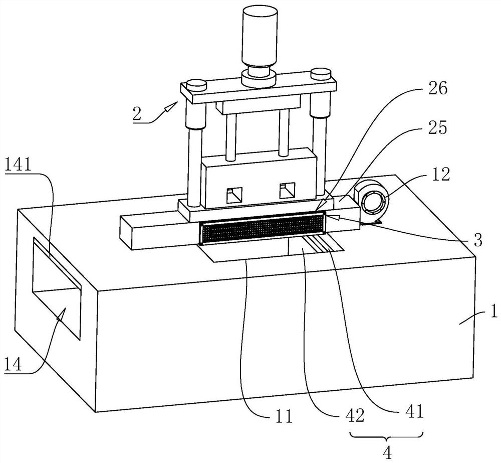
[0040] The embodiment of the present application discloses a punching equipment for processing sheet metal parts. refer to figure 2 A punching device for processing sheet metal parts includes a workbench 1 and a machine body 2 . The machine body 2 is vertically seated on the top wall of the workbench 1 for punching the workpiece. A settling tank 11 is arranged on the top wall of the workbench 1 and below the machine body 2 . When the workpiece punches on the machine body 2 and moves relative to the width direction of the machine body 2, the waste generated by the workpiece opening can break away from the workpiece under the action of gravity and fall into the inner cavity of the settling tank 11, thereby reducing the waste on the top of the workbench 1. The phenomenon of wall accumulation.

[0041] refer to figure 2 , 3 One end of the top wall of the workbench 1 and lo...


PUM


Abstract

The invention relates to punching equipment for sheet metal part machining and a material collecting technology of the punching equipment. The punching equipment comprises a workbench and a machine body, the machine body is arranged on the top wall of the workbench, a settling tank used for containing waste is arranged at the position, located below the machine body, on the top wall of the workbench, and the inner width of the settling tank is larger than the outer width of the machine body. A material collecting part is arranged at the position, in the settling tank, of the workbench, the material collecting part comprises a bearing box and a material gathering box, and the material gathering box is arranged in an inner cavity of the bearing box. A discharging hole with an inner cavity communicating with the settling tank is formed in the outer side wall of the workbench, a side groove is formed in the position, located at the end, away from the discharging hole, of the settling tank, of the outer side wall of the workbench, and a driving part used for pushing the material collecting part to the discharging hole is arranged in the side groove of the workbench. The material collecting technology of the punching equipment comprises the steps of collecting waste, clearing and transporting the waste and installing a new box. The punching equipment and the material collecting technology have the effects that the phenomenon that waste is accumulated on the top wall of the workbench is effectively reduced, and the waste clearing and transporting efficiency of operators is improved.

Description

technical field [0001] The present application relates to the field of sheet metal parts processing equipment, in particular to a punching equipment for sheet metal part processing and a material receiving process thereof. Background technique [0002] At present, punching equipment is often used in the production and processing of thin and light sheet metal workpieces such as hollow tubes. The punching equipment can form a certain number of through holes on the workpiece, so that the workpiece can meet the needs of subsequent production and processing. [0003] The related art discloses a punching equipment for processing sheet metal parts, refer to figure 1 , including workbench 1 and body 2. The body 2 is arranged on the top wall of the workbench 1 , and the body 2 includes a base support 21 , two guide columns 22 , a receiving plate 23 and an air cylinder 24 . The two guide posts 22 are vertically arranged on the top wall of the bottom support base 21 , and a fixing b...

Claims


Application Information

Patent Timeline
Patent Type & Authority Applications(China)
IPC IPC(8): B21D28/34B21D43/20B21D45/00
CPCB21D28/34B21D43/20B21D45/00
Inventor 徐胜
Owner 上海通成企业发展有限公司
Why Eureka
Try Eureka