
A Continuously Adjustable Air Inlet Venting Device

A technology of deflation device and air inlet, which is applied in the direction of jet propulsion device, gas turbine device, machine/engine, etc. It can solve the problems of transmission stability limitation, slow response speed, high-temperature fluid leakage, etc., and achieve continuously adjustable deflation volume , the amount of deflation is avoided, and the effect of improving performance

Active Publication Date: 2022-02-08
NANJING UNIV OF AERONAUTICS & ASTRONAUTICS +1
View PDF6 Cites 0 Cited by
  • Summary
  • Abstract
  • Description
  • Claims
  • Application Information

AI Technical Summary

Problems solved by technology

This scheme integrates the inner pressure section of the encircled city inlet on the lower surface of the aircraft, the throat and the casing of the combustion chamber as a whole, which has a great impact on the overall design of the aircraft and is difficult to achieve in practical applications.
(4) New adjustment technology, including flexible adjustable inlet technology and memory alloy adjustment scheme, which has strong potential in aviation, but also has problems such as poor high temperature resistance and slow response speed in engineering applications
However, the space of hypersonic vehicles is very limited, the working environment is harsh, and there are strong geometric constraints on the shape and operating range of the rotating mechanism. In addition, in most cases, the motor shaft and the blade shaft cannot be directly driven. There are many problems: the dead point of the four-bar linkage mechanism will lead to double solutions in motion, and the transmission reliability is poor; because the air release chamber is generally placed on both sides of the air inlet, the space is extremely limited, and a complete gear cannot be arranged, even if it can Arrangement, due to the small space and the small number of teeth of the gear, it is difficult to realize the infinite rotation of the micro-blade; because there will inevitably be high-temperature fluid leakage in the driving device, the transmission stability of the belt drive in a high-temperature environment is also limited

Method used


Image

  • A Continuously Adjustable Air Inlet Venting Device
  • A Continuously Adjustable Air Inlet Venting Device
  • A Continuously Adjustable Air Inlet Venting Device

Examples


Embodiment Construction

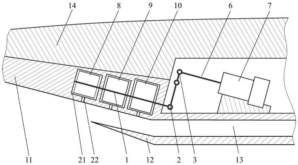
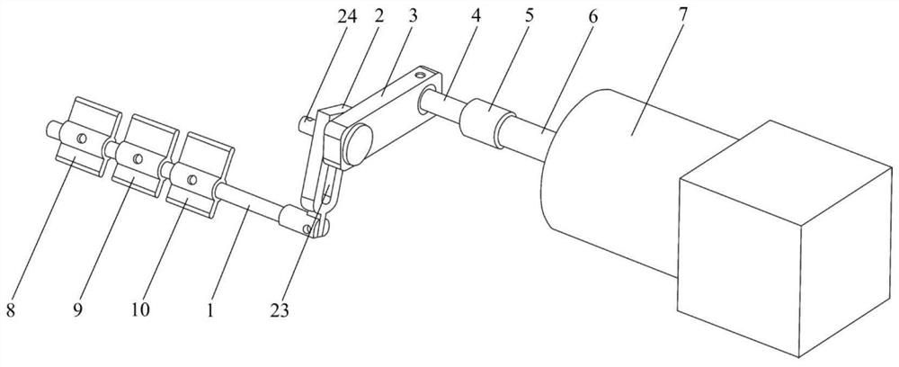
[0020] Please combine figure 1 and figure 2 As shown, the present invention proposes a continuously adjustable air intake deflation device, which includes an air intake precursor 14, a compression surface 11 formed on the outer surface of the precursor, an air intake lip cover 12, and a driving module. An inner chamber 20 is provided in the air intake precursor body, and several air release grooves 21 located inside the compression surface are also provided in the air inlet precursor body, and both sides of the air release grooves 21 communicate with the outside of the air intake channel. An opening 22 passing through the compression surface is provided between the air release groove 21 and the compression surface 11 , and the opening 22 communicates with the air release groove 21 .

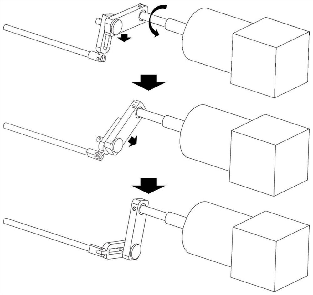
[0021] The drive module includes a motor 7 located in the inner cavity, blades 8, 9, 10 located in the air release groove 21, an output shaft 1 connected to the blades and driving the blades to...


PUM


Abstract

The invention discloses a continuously adjustable air intake device. A number of air release grooves located inside the compression surface are arranged in the front body of the air intake port. The two sides of the air release grooves communicate with the outside of the air intake port. An opening penetrating through the compression surface is provided between the air groove and the compression surface, and the opening communicates with the air release groove. It also includes a drive module, the drive module includes a motor located in the inner chamber, a vane located in the air release slot, and the vane opens or closes the air release slot through rotation. The air inlet exhaust device has a simple structure, continuously adjustable air release volume and avoids the interference of dead points; Range adjustment, and there is no special requirement for the direction of rotation; since the rotation angle of the motor is known, the rotation angle of the blade can be known without additional sensors to monitor the rotation angle.

Description

technical field [0001] The invention relates to the field of hypersonic inlet aerodynamic experiments, in particular to a continuously adjustable inlet deflation device. Background technique [0002] As one of the key components of the aircraft, the performance of the hypersonic inlet directly affects the propulsion efficiency of the propulsion system and even the overall performance of the aircraft. However, the low Mach number of the hypersonic inlet has a poor starting ability, which limits the capability of the aircraft. Therefore, the aircraft must use other power devices at low Mach numbers. This not only makes the structure more complex, but also affects the cost of hypersonic flight. [0003] Generally, the methods for reducing the starting Mach number of the intake port can be divided into two categories: variable geometry methods and other methods under fixed geometry conditions. Because the performance of the conventional fixed-geometry inlet varies greatly unde...

Claims


Application Information

Patent Timeline
Patent Type & Authority Patents(China)
IPC IPC(8): F02C7/057
CPCF02C7/057
Inventor 黄河峡秦源唐学斌林正康谭慧俊张航王梓任李超徐翕如
Owner NANJING UNIV OF AERONAUTICS & ASTRONAUTICS
Learn More