Relay and parameter correction method of relay

A relay and integrated technology, applied in the field of relay parameter correction and electromagnetic relay, to achieve the effect of high adjustment efficiency and low manufacturing requirements

Pending Publication Date: 2021-07-13
XIAMEN HONGFA ELECTRIC POWER CONTROLS
View PDF1 Cites 0 Cited by
  • Summary
  • Abstract
  • Description
  • Claims
  • Application Information

AI Technical Summary

Problems solved by technology

Although this solution can be adjusted relatively conveniently, it increases the manufacturing process requirements of the reed

Method used


Image

  • Relay and parameter correction method of relay
  • Relay and parameter correction method of relay
  • Relay and parameter correction method of relay

Examples


Embodiment 1

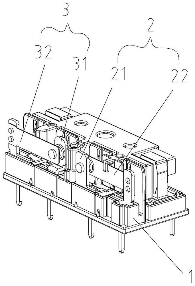
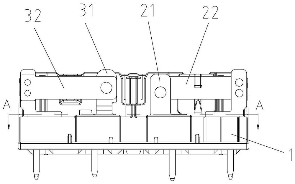
[0046] Such as figure 1As shown, this embodiment provides a relay, including a base 1, a contact assembly and an electromagnetic actuation assembly mounted on the base 1, wherein the contact assembly includes a first reed set 2 and a second reed set 3. It is used to control the on-off of the two circuits respectively. The first reed group 2 includes the first static reed 21 and the first moving reed 22 arranged at intervals, and the second reed group 3 includes the second static reeds arranged at intervals. Reed 31 and the second movable reed 32, the first static reed 21 is oppositely arranged on the outer side of one end of the first movable reed 22, and the second static reed 31 is oppositely arranged on the outer side of one end of the second movable reed 32 position, the first static reed 21, the first moving reed 22, the second static reed 31 and the second moving reed 32 all have conductive contacts, and the electromagnetic actuation assembly (usually including coil, yok...

Embodiment 2

[0056] Such as Figure 11 As shown, this embodiment provides a relay, including a base 4, a contact assembly and an electromagnetic actuation assembly installed on the base 4, wherein the contact assembly includes a static reed 5 and a movable reed 6 arranged at intervals , both the static reed 5 and the movable reed 6 have conductive contacts, driven by the electromagnetic actuation assembly, the movable reed 6 can establish contact or separation of the conductive contacts with the static reed 5, thereby realizing the conduction of the circuit on or off.

[0057] Different from Embodiment 1, the static reed 5 and the moving reed 6 in this embodiment are relatively upright and arranged side by side, and both the static reed 5 and the moving reed 6 are fixedly inserted on the base 4, Such as Figure 14-15 The base 4 is provided with a first insertion card slot 41 and a second insertion card slot 42, and the static reed 5 and the moving reed 6 are inserted and fixed in the fir...

Embodiment 3

[0064] This embodiment proposes a parameter calibration method for a relay, including the following steps:

[0065] A. Provide a set relay, the relay may be the relay of Embodiment 1 and Embodiment 2 above or other modified embodiments equivalent to the structural principle of the two.

[0066] B. Change the convex height of the convex hull on either side or both sides of the two sheet surfaces on the reed that needs to be adjusted (that is, adjust the convex hull adjustment structure), so that the reed produces a positive or negative angle compared to the original The swing deflection until the distance and angle between the conductive contact on the reed to be adjusted and another conductive contact meets the mechanical or electrical parameter requirements; this step B can be performed on the production line to achieve rapid real-time adjustment.

[0067] C, Insert the assembly reed into the insertion card slot of the base.


PUM


Abstract

The invention relates to a relay and a parameter correction method of the relay, the relay comprises a base and two reeds arranged on the base, each reed is provided with a first reed body surface and a second reed body surface which are deviated from each other, and the base is provided with a plugging clamping groove corresponding to a fixed assembling position of the reed. At least one reed is provided with a first convex hull on the surface of a first reed body and a second convex hull on the surface of a second reed body, the first convex hull and the second convex hull are arranged on the orthographic projection surface of the reed body at an interval, and a rotating axis is formed between the first convex hull and the second convex hull; the reed is inserted into the plugging clamping groove and is fixed with the plugging clamping groove through interference fit of the first convex hull and the second convex hull, and the reed is adjusted by changing the protruding height of the first convex hull and/or the second convex hull, so that the reed can swing around the rotating axis; and therefore, the spacing distance between the conductive contact on one reed and the conductive contact on the other reed can be adjusted and changed.

Description

technical field [0001] The invention relates to a relay, especially an electromagnetic relay using a reed as a contact assembly, and also relates to a parameter correction method of the relay. Background technique [0002] Electromagnetic relays, including push-type electromagnetic relays or snap-in relays, etc., usually have a structure including: a base, an outer shell fixed on the base, and a contact assembly and an electromagnetic actuating assembly arranged in the outer shell. The contact assembly is usually composed of one or more sets of static reeds or moving reeds (collectively referred to as "reeds") with contacts. Driven by the electromagnetic actuation component, the moving reed is respectively in contact with or separated from the established contact of the static reed, so as to realize different circuit conduction or opening and closing (called switch switching); the electromagnetic actuation component is mainly It consists of an armature, a yoke, a coil, and ...

Claims


Application Information

Patent Timeline
Patent Type & Authority Applications(China)
IPC IPC(8): H01H45/14H01H57/00
CPCH01H45/14H01H57/00
Inventor 钟叔明代文广何仲波罗泽宇
Owner XIAMEN HONGFA ELECTRIC POWER CONTROLS
Why Eureka
Try Eureka