Linear motor adjusting structure for track system

A linear motor and structure adjustment technology, which is applied in the field of rail transit, can solve the problems of high processing difficulty, high processing cost, high installation and debugging cost, and difficulty in ensuring accuracy, and achieve small deformation, reduce installation and use costs and later labor costs, The effect of lowering the altitude

Inactive Publication Date: 2022-03-04
AEROSPACE HI TECH HLDG GROUP
View PDF6 Cites 0 Cited by
  • Summary
  • Abstract
  • Description
  • Claims
  • Application Information

AI Technical Summary

Problems solved by technology

[0004] In order to solve the existing rail connection, the left and right rails are connected with a screw rod after clamping the lower edge of the rail with a clamp. It is difficult to realize the position height of the motor installed on the screw rod, the processing difficulty is high, and the accuracy after installation is difficult to guarantee. The problem of uniformity after batching, high processing cost and installation and debugging cost, and then provide a linear motor adjustment structure for track system

Method used


Image

  • Linear motor adjusting structure for track system
  • Linear motor adjusting structure for track system
  • Linear motor adjusting structure for track system

Examples


specific Embodiment approach 1

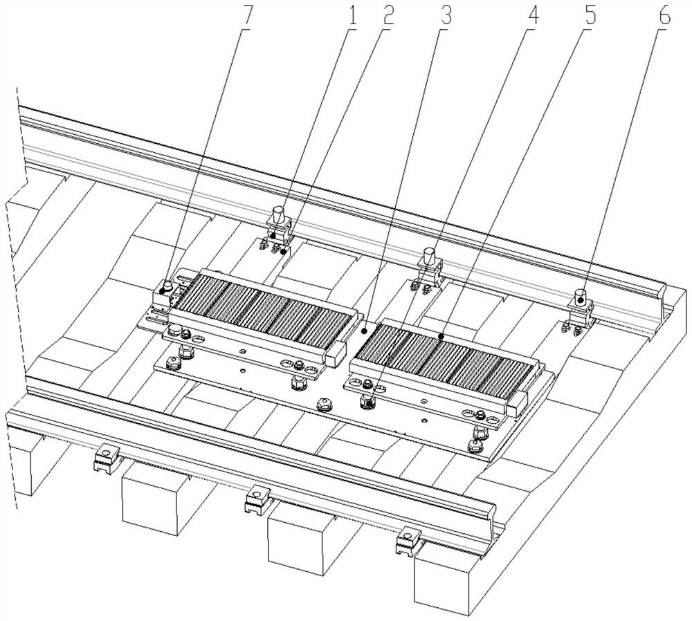
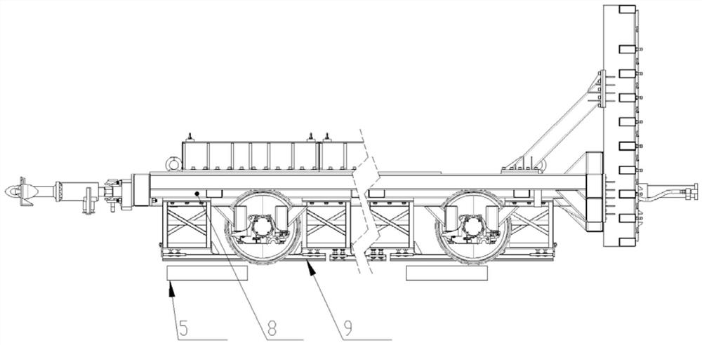
[0017] Specific implementation mode one: combine Figure 1-Figure 2 Describe this embodiment, the linear motor adjustment structure for the track system, which includes a support frame, a mounting plate 3, a position sensor 7, two linear motors 5, a plurality of height detection sensors 6 and a plurality of electric push rods 4; the mounting plate 3 is installed on the bottom end of the track through a support frame, and two linear motors 5 are installed on the mounting plate 3 along the length direction, and each linear motor 5 is mounted on the mounting plate 3 through a plurality of electric push rods 4, and the A height detection sensor 6 is installed on the support frame along the length direction, and the position sensor 7 is installed on the linear motor 5 on the side where the track is the entry end.

[0018] The electric push rod 4, the linear motor 5, the height detection sensor 6 and the position sensor 7 are connected to the external PLC controller, and the height ...

specific Embodiment approach 2

[0019] Specific implementation mode two: combination Figure 1-Figure 2 Describe this embodiment, a linear motor adjustment structure for a track system described in this embodiment, the support frame includes a plurality of connecting plates 2 and a plurality of track clamps 1; two ends of each connecting plate 2 are respectively installed with a track The clamp 1 and the connecting plate 2 are installed on the track through two track clamps 1 . Other compositions and connection methods are the same as those in Embodiment 1.

specific Embodiment approach 3

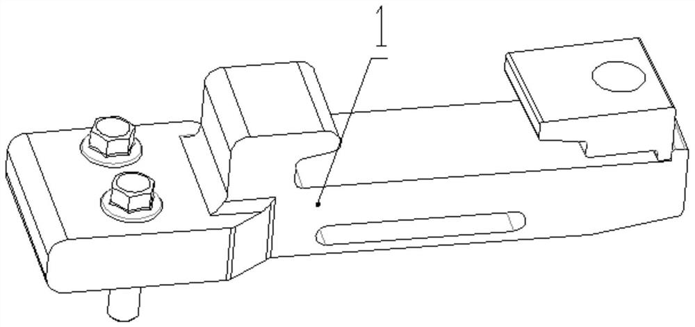
[0020] Specific implementation mode three: combination Figure 1-Figure 2 Describe this embodiment, a linear motor adjustment structure for a rail system described in this embodiment, the rail clamp 1 includes a fixed block, a fixed block and a movable block; the fixed block is installed on the fixed block, and the movable block passes through The bolts are fixedly installed on the fixed block, and the fixed block and the movable block are relatively arranged and installed on the bottom end of the rail, and each fixed block is fixedly installed on one end of the connecting plate 2 by bolts. Other compositions and connection methods are the same as those in the second embodiment.


PUM


Abstract

The invention discloses a linear motor adjusting structure for a track system, relates to a motor adjusting structure, and aims to solve the problems that a left track and a right track are connected by a lead screw after clamping the lower edge of the track by a fixture, the height of a motor mounted on the lead screw is difficult to realize, the processing difficulty is high, and the precision after mounting is difficult to guarantee; the device comprises a support frame, a mounting plate, a position sensor, two linear motors, a plurality of height detection sensors and a plurality of electric push rods, the mounting plate is mounted at the bottom end of the track through the supporting frame, the two linear motors are mounted on the mounting plate in the length direction, each linear motor is mounted on the mounting plate through the multiple electric push rods, the multiple height detection sensors are mounted on the supporting frame in the length direction, and the position sensor is mounted on the linear motor on the side, which is the inlet end, of the track. The invention belongs to the field of rail transit.

Description

technical field [0001] The invention relates to a motor adjustment structure, in particular to a linear motor adjustment structure used in a rail system, and belongs to the field of rail transportation. Background technique [0002] As the national coverage of my country's rail transit network is getting higher and higher, the rail transit mode of train, high-speed rail and subway has become a more convenient choice for people to travel, and the subsequent safety issues have become a hot spot of concern. Rail vehicles need to conduct strict safety experiments on trains, high-speed rails, etc., the most important of which is the crash test, which requires linear motors to be installed on the track plane. The basic requirement for installing the motor is that no drilling or other damage to the track and sleeper is allowed. In order to make the motor output the maximum torque, it is necessary to ensure that the distance between the linear motor installed on the track and the se...

Claims


Application Information

Patent Timeline
Patent Type & Authority Applications(China)
IPC IPC(8): H02K5/26H02K5/00H02K41/02
CPCH02K5/26H02K5/00H02K41/02
Inventor 刘金泽孟繁越王耀文宋丹丹
Owner AEROSPACE HI TECH HLDG GROUP
Why Eureka
Try Eureka